1035 THE SHOCK-PATTERNED SOLAR CHROMOSPHERE IN THE LIGHT OF ALMA S. Wedemeyer-B¨ ohm
advertisement
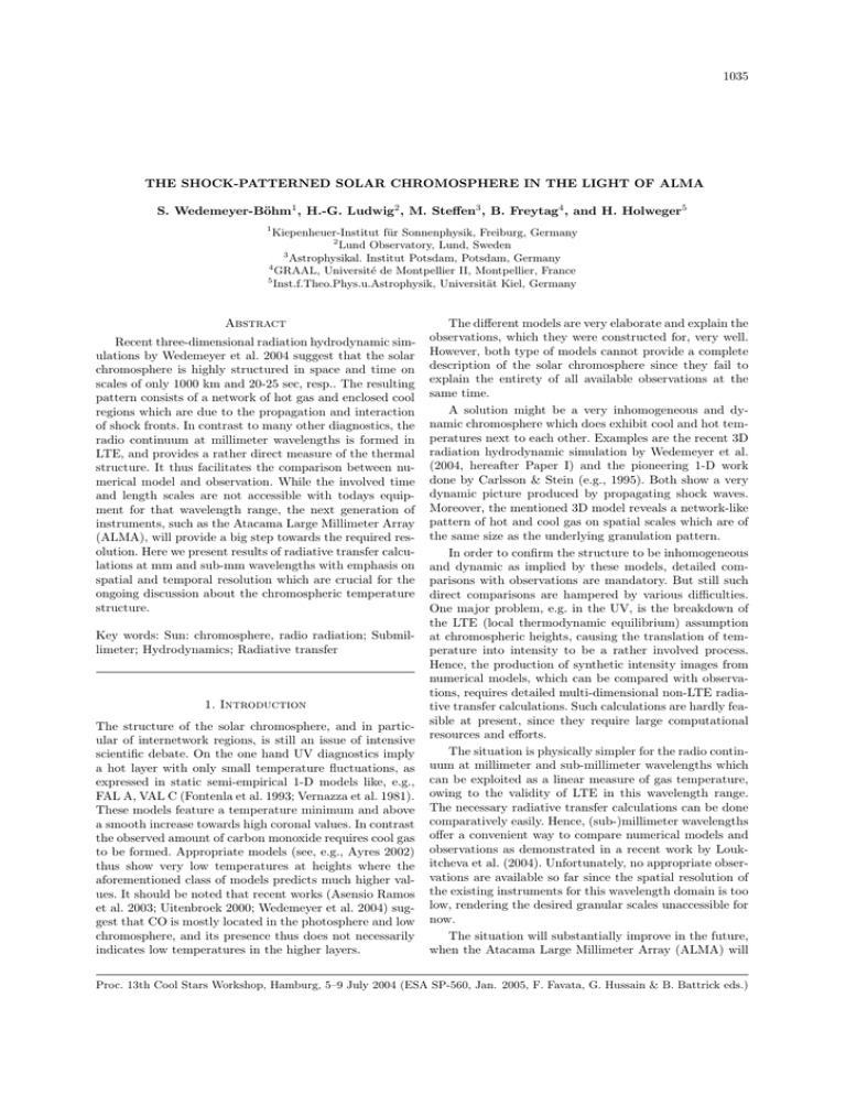
1035 THE SHOCK-PATTERNED SOLAR CHROMOSPHERE IN THE LIGHT OF ALMA S. Wedemeyer-Böhm1 , H.-G. Ludwig2 , M. Steffen3 , B. Freytag4 , and H. Holweger5 1 Kiepenheuer-Institut für Sonnenphysik, Freiburg, Germany 2 Lund Observatory, Lund, Sweden 3 Astrophysikal. Institut Potsdam, Potsdam, Germany 4 GRAAL, Université de Montpellier II, Montpellier, France 5 Inst.f.Theo.Phys.u.Astrophysik, Universität Kiel, Germany Abstract Recent three-dimensional radiation hydrodynamic simulations by Wedemeyer et al. 2004 suggest that the solar chromosphere is highly structured in space and time on scales of only 1000 km and 20-25 sec, resp.. The resulting pattern consists of a network of hot gas and enclosed cool regions which are due to the propagation and interaction of shock fronts. In contrast to many other diagnostics, the radio continuum at millimeter wavelengths is formed in LTE, and provides a rather direct measure of the thermal structure. It thus facilitates the comparison between numerical model and observation. While the involved time and length scales are not accessible with todays equipment for that wavelength range, the next generation of instruments, such as the Atacama Large Millimeter Array (ALMA), will provide a big step towards the required resolution. Here we present results of radiative transfer calculations at mm and sub-mm wavelengths with emphasis on spatial and temporal resolution which are crucial for the ongoing discussion about the chromospheric temperature structure. Key words: Sun: chromosphere, radio radiation; Submillimeter; Hydrodynamics; Radiative transfer 1. Introduction The structure of the solar chromosphere, and in particular of internetwork regions, is still an issue of intensive scientific debate. On the one hand UV diagnostics imply a hot layer with only small temperature fluctuations, as expressed in static semi-empirical 1-D models like, e.g., FAL A, VAL C (Fontenla et al. 1993; Vernazza et al. 1981). These models feature a temperature minimum and above a smooth increase towards high coronal values. In contrast the observed amount of carbon monoxide requires cool gas to be formed. Appropriate models (see, e.g., Ayres 2002) thus show very low temperatures at heights where the aforementioned class of models predicts much higher values. It should be noted that recent works (Asensio Ramos et al. 2003; Uitenbroek 2000; Wedemeyer et al. 2004) suggest that CO is mostly located in the photosphere and low chromosphere, and its presence thus does not necessarily indicates low temperatures in the higher layers. The different models are very elaborate and explain the observations, which they were constructed for, very well. However, both type of models cannot provide a complete description of the solar chromosphere since they fail to explain the entirety of all available observations at the same time. A solution might be a very inhomogeneous and dynamic chromosphere which does exhibit cool and hot temperatures next to each other. Examples are the recent 3D radiation hydrodynamic simulation by Wedemeyer et al. (2004, hereafter Paper I) and the pioneering 1-D work done by Carlsson & Stein (e.g., 1995). Both show a very dynamic picture produced by propagating shock waves. Moreover, the mentioned 3D model reveals a network-like pattern of hot and cool gas on spatial scales which are of the same size as the underlying granulation pattern. In order to confirm the structure to be inhomogeneous and dynamic as implied by these models, detailed comparisons with observations are mandatory. But still such direct comparisons are hampered by various difficulties. One major problem, e.g. in the UV, is the breakdown of the LTE (local thermodynamic equilibrium) assumption at chromospheric heights, causing the translation of temperature into intensity to be a rather involved process. Hence, the production of synthetic intensity images from numerical models, which can be compared with observations, requires detailed multi-dimensional non-LTE radiative transfer calculations. Such calculations are hardly feasible at present, since they require large computational resources and efforts. The situation is physically simpler for the radio continuum at millimeter and sub-millimeter wavelengths which can be exploited as a linear measure of gas temperature, owing to the validity of LTE in this wavelength range. The necessary radiative transfer calculations can be done comparatively easily. Hence, (sub-)millimeter wavelengths offer a convenient way to compare numerical models and observations as demonstrated in a recent work by Loukitcheva et al. (2004). Unfortunately, no appropriate observations are available so far since the spatial resolution of the existing instruments for this wavelength domain is too low, rendering the desired granular scales unaccessible for now. The situation will substantially improve in the future, when the Atacama Large Millimeter Array (ALMA) will Proc. 13th Cool Stars Workshop, Hamburg, 5–9 July 2004 (ESA SP-560, Jan. 2005, F. Favata, G. Hussain & B. Battrick eds.) S. Wedemeyer-Böhm et al. 5.0 3000 4.0 2000 3.0 1000 b 5.0 2000 3. The hydrodynamic model Here we use the numerical 3D model described in Paper I which has been calculated with the radiation hydrodynamics code CO5 BOLD (Freytag et al. 2002). Magnetic fields are not included, restricting the model to internetwork regions. The resolution of the model atmosphere is 40 km in horizontal (x, y) and 12 km in vertical direction (z). The top of the model is located at a height of z = 1710 km in the middle chromosphere. The origin of the z axis is defined by the level where the average Rosseland optical depth reaches unity. Since the horizontal extension is 5600 km, the model represents a quadratic patch of 7. 7 × 7. 7 of a non-magnetic internetwork region like it should be observable with ALMA. 1000 5000 4.0 c 5.5 5.0 4000 y [km] 4.5 3000 4.0 2000 3.5 1000 5000 3.0 d 8.0 4000 y [km] The Atacama Large Millimeter Array (ALMA) will consist of 64 telescopes with diameters of 12 m each, setting up 2016 baselines. The full array will start operation in 2011 in the Chilean Andes. There will be ten frequency bands which cover a total range from 31.3 GHz (λ = 9.58 mm) to 950 GHz (λ = 0.32 mm). According to Bastian (2002), ALMA will provide an angular resolution of 0. 015 to 1. 4, depending on antenna configuration. This corresponds to only ∼ 10 km to ∼ 1000 km on the Sun. However, ALMA will not sample both these small spatial scales and the larger scales needed to reconstruct the entire field of view (e.g., 21 at λ = 1 mm or about the size of the interior of an internetwork region) simultaneously. Rather, the effective resolution may be limited by the number of pieces of information measured instantaneously: 2016 resolution elements (due to the number of baselines) correspond to an effective resolution of about 0.5 at λ = 1 mm. A major advantage of ALMA for solar research lies in the properties of its wavelength range because (i) gas temperature linearly translates into emergent continuum intensity and (ii) synthetic intensity images for comparison can be calculated comparatively easily. intensity at λ = 1.0 mm 2. Atacama Large Millimeter Array y [km] 6.0 3000 intensity at λ = 0.3 mm 4000 [10−4 erg cm−2 s−1 Å−1 sr−1] 7.0 [10−6 erg cm−2 s−1 Å−1 sr−1] 5000 [1000 K] 6.0 4000 temperature at z = 1000 km 7.0 a intensity at λ = 9.0 mm 5000 [10−10 erg cm−2 s−1 Å−1 sr−1] commence operation (∼ 2011). This instrument will provide high spatial and temporal resolution, allowing to observe the small-scale structure of the solar chromosphere. Here we present images of emergent continuum intensity at millimeter wavelengths which are calculated from the recent three-dimensional radiation hydrodynamics simulation by Wedemeyer et al. (2004). Since the simulation does not include magnetic fields, the presented analysis refers to non-magnetic internetwork regions only. Our aim is to predict how those areas would be seen by instruments like ALMA. A detailed paper with supplementary calculations is in preparation. y [km] 1036 7.0 3000 6.0 2000 5.0 1000 4.0 1000 2000 3000 x [km] 4000 5000 Figure 1. Exemplary horizontal maps, all calculated from the same simulation snapshot: a) gas temperature at a geometrical height of z = 1000 km, and b-d) emergent continuum intensity at wavelengths of 0.3 mm, 1 mm, and 9 mm, respectively. The legend next to each panel indicates data range and colourcoding. All images are calculated for disk-center. The model chromosphere is dominated by shock waves which are excited in the lower layers. Propagation and interaction of these waves give the model chromosphere its characteristic appearance: thin filaments of hot gas (shock waves) and embedded cool regions (see Fig. 1a). The mesh size of this network-like pattern is comparable to spatial scales typical for granulation. The average chromospheric temperature is roughly 3700 K but spans a large range The shock-patterned solar chromosphere in the light of ALMA 1.0 a: Tgas, z = 1000 km contribution 0.03 0.02 0.01 0.00 2 3 distr. func. 0.04 4 temperature [103 K] 5 6 0.01 0.5 0.6 intensity [10-3 erg cm-2 s-1 ¯-1] 0.04 distr. func. 0.4 0.02 0.4 a: 0.3 mm 0.6 0.0 1.0 0.03 0.00 0.7 c: I, λ = 1.0 mm 0.03 0.8 480 km b: 1 mm 0.6 0.4 0.2 0.02 0.0 1.0 0.01 2.5 3.0 3.5 4.0 4.5 intensity [10-6 erg cm-2 s-1 ¯-1] 0.04 5.0 5.5 d: I, λ = 9.0 mm 0.03 0.02 contribution 0.00 distr. func. 0.8 0.2 b: I, λ = 0.3 mm contribution distr. func. 0.04 1037 0.8 580 km c: 9 mm 0.6 0.4 0.2 0.01 0.00 0.3 0.4 0.5 0.6 intensity [10-9 erg cm-2 s-1 ¯-1] 0.7 0.8 Figure 2. Histograms for a) gas temperature in a horizontal slice at geometrical height z = 1000 km, and b-d) emergent continuum intensity at wavelengths of 0.3 mm, 1 mm, and 9 mm, respectively. from only ∼ 2000 K to over 7000 K in shock waves. Caused by the large velocity of these waves, the whole pattern changes on time scales of only 20-25 s (1/e autocorrelation time scale). As mentioned in Paper I the radiative transfer in the simulation still needs to be improved for chromospheric conditions whereas the lower layers are modelled very realistically (see, e.g., Leenaarts & Wedemeyer-Böhm, submitted). The absolute temperature amplitudes are thus somewhat uncertain and need to be calibrated against observations. In contrast, the general topology of the upper layers (up to heights where magnetic fields become nonnegligible) is a robust feature. The shock waves, which produce the pattern, are generated in the lower well-modelled layers, and their propagation and interaction does not sensitively depend on the thermodynamics of the chromospheric layers. Although the temperature amplitudes must be considered with caution, the model nevertheless provides insight in the involved spatial and temporal scales and thus can help to define constraints for future observations. 4. Radiative transfer calculations The continuum at (sub-)millimeter wavelengths originates from the low and middle chromosphere and is mainly due to thermal free-free radiation. The assumption of local 0.0 200 (780 km) 400 600 800 1000 z [km] 1340 km 1200 1400 1600 Figure 3. Normalised averaged intensity contribution functions on the geometrical height scale of the simulation sequence at wavelengths of a) 0.3 mm, b) 1 mm, and c) 9 mm. The vertical lines mark the height of maximum contribution (dashed), of half the integrated function (dot-dashed), and the boundary photosphere/chromosphere (dotted). thermodynamic equilibrium (LTE) is valid and the source function is Planckian. Furthermore, hν kB T , allowing to use the Rayleigh-Jeans approximation. Consequently, the source function is linearly related to the local gas temperature at these wavelengths. These conditions largely simplify the necessary calculations. The continuous opacity at mm and sub-mm wavelengths goes roughly proportional to the electron pressure. Carlsson & Stein (2002) showed that the ionisation fraction of hydrogen — becoming the major electron contributor at chromospheric heights — exhibits substantial deviations from thermodynamic equilibrium conditions. The ionisation fraction of hydrogen cannot follow the rapid changes of the thermodynamic conditions associated with the passage of shock waves but tends to stay on a fixed level characteristic for the hot, shocked gas phase. In comparison to LTE conditions this leads to a systematic increase of the opacity, particularly in the cool, largely neutral regions. On average we expect a shift of the emitting layers towards larger heights, and an increase of intensity contrasts. The important deviations from thermodynamic equilibrium of the hydrogen ionisation have not been taken into account in the spectrum synthesis calculations of this preliminary study but should be considered in more de- 1038 S. Wedemeyer-Böhm et al. tailed calculations. We nevertheless think that the relative spatial and temporal statistics of the intensity fluctuations is still reasonably represented by our simplified model. The continuum images, which are presented here (see Fig. 1), were computed with the 3D LTE spectrum synthesis code LINFOR3D, which was developed by Steffen & Ludwig (based on the Kiel code LINFOR/LINLTE). For convenience we adopt the following wavelengths for the spectrum synthesis, covering the range accessible by ALMA: 0.3 mm (∼ 1000 GHz), 1 mm (∼ 300 GHz), and 9 mm (∼ 33 GHz). All calculations are done for diskcenter (µ = 1.0). In principle, the temporal evolution of the chromospheric structure depends on the sampled height range, too. But since the evolution time scale (see Paper I) stays roughly constant throughout the model chromosphere, the intensity maps evolve on the same time scales (20-25 s). Finally, we degraded the spatial resolution with a Gauss profile. The small-scale pattern is clearly visible at 0. 5 (FWHM). At 1 , however, the image is very blurred but still exhibits fluctuations on granular scales. But the intensity contrast decreases strongly with resolution, complicating the detection of the pattern at resolutions above 1 . Pushing the effective resolution as high as possible is thus clearly of crucial importance. These matters are discussed in more detail in a forthcoming paper. 5. Results The horizontal temperature cross-section in Fig.1a shows a pattern which is characteristic for the model chromosphere. The intensity maps in Fig. 1b-d look more or less similar but with different contributions of dark and bright areas as can also be seen in the histograms in Fig. 2. The gas temperature distribution at z = 1000 km (panel a) exhibits two separate peaks, one at high temperatures due to hot shock waves and one at low values, caused by the cool background. The model shows a similar picture for all chromospheric heights above ∼ 800 km where shock waves become clearly visible (see Paper I for more details). The layers below are characterised by a single peak with a height-dependent width. The differences in the intensity histograms are therefore directly caused by the mapping of different height ranges, from where the continuum intensity emerges, thus sampling different sets of gas temperatures. The height ranges can be seen in Fig. 3 in the form of intensity contribution functions. At 0.3 mm the maximum intensity contribution originates from the upper photosphere (z = 480 km), whereas the chromosphere contributes only little compared to the intensity at 1 mm. At that wavelength the middle chromosphere produces a significant fraction, while the maximum is still located in the very low chromosphere (z = 580 km). Consequently, the intensity distribution at 1 mm is much more similar to the gas temperature at z = 1000 km compared to λ = 0.3 mm which mostly samples the high photosphere. At 9 mm, however, the intensity is due to a large height range throughout the whole model chromosphere, even exceeding its vertical extent. Hence, a significant part of the emergent radiation at λ = 9 mm would come from layers not included in the model, so that the results derived for this wavelength should be interpreted with great care. The clear tendency of sampling higher layers as one goes to longer wavelength is expected since the opacity scales as the wavelength squared. The rapid increase of the opacity towards longer wavelength is associated with a shift of the continuum forming layers towards correspondingly lower density. 6. Conclusions A comparison with future ALMA observations will form a strong test for present and future models of the solar atmosphere. As shown with these exemplary calculations, emergent continuum intensity at different wavelengths samples different height ranges of the (model) chromosphere. Hence, simultaneous observations at multiple wavelengths will provide substanial new insight in the hitherto hotly debated structure of the solar chromosphere. Given this powerful tool, also the propagation of shock waves and chromospheric oscillation modes can be addressed. However, as we did show in this work, high spatial and temporal resolution are of crucial importance for observing the small-scale structure of internetwork regions, whereas the field of view just needs to be large enough to cover a reasonable part of an internetwork region. Acknowledgements We thank T. Ayres, R. Osten, and S. White for helpful comments. References Asensio Ramos, A., Trujillo Bueno, J., Carlsson, M., & Cernicharo, J., 2003, ApJL, 588, L61 Ayres, T. 2002, ApJ, 575, 1104 Bastian, T. S. 2002, Astron.Nachr., 323, 271 Carlsson, M. & Stein, R. F. 1995, ApJL, 440, L29 Carlsson, M. & Stein, R. F. 2002, ApJ, 572, 626 Freytag, B., Steffen, M., & Dorch, B. 2002, Astron. Nachr., 323, 213 Fontenla, J. M., Avrett, E. H., & Loeser, R. 1993, ApJ, 406, 319 Leenaarts, J., & Wedemeyer-Böhm, S., A&A, submitted Loukitcheva, M., Solanki, S. K., Carlsson, M., & Stein, R. F., 2004, A&A 419, 747 Uitenbroek, H. 2000, ApJ, 531, 571 Vernazza, J. E., Avrett, E. H., & Loeser, R. 1981, ApJS, 45, 635 Wedemeyer, S., Freytag, B., Steffen, M., Ludwig, H.-G., & Holweger, H. 2004, A&A 414, 1121

