ES201 – Fall 2003-2004 Instructor: _____________________
advertisement
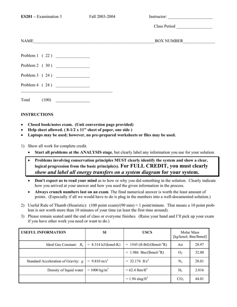
ES201 – Examination 3 Fall 2003-2004 Instructor: _____________________ Class Period _________________ NAME_________________________________________________________BOX NUMBER_______________ Problem 1 ( 22 ) ________________ Problem 2 ( 30 ) ________________ Problem 3 ( 24 ) ________________ Problem 4 ( 24 ) ________________ ___________________________________________ Total (100) ________________ INSTRUCTIONS • • • Closed book/notes exam. (Unit conversion page provided) Help sheet allowed. ( 8-1/2 x 11" sheet of paper, one side ) Laptops may be used; however, no pre-prepared worksheets or files may be used. 1) Show all work for complete credit. • Start all problems at the ANALYSIS stage, but clearly label any information you use for your solution. • Problems involving conservation principles MUST clearly identify the system and show a clear, logical progression from the basic principle(s). For FULL CREDIT, you must clearly show and label all energy transfers on a system diagram for your system. • • Don't expect us to read your mind as to how or why you did something in the solution. Clearly indicate how you arrived at your answer and how you used the given information in the process. Always crunch numbers last on an exam. The final numerical answer is worth the least amount of points. (Especially if all we would have to do is plug in the numbers into a well-documented solution.) 2) Useful Rule of Thumb (Heuristic): (100 point exam)/(90 min) ≈ 1 point/minute. That means a 10 point problem is not worth more than 10 minutes of your time (at least the first time around). 3) Please remain seated until the end of class or everyone finishes. (Raise your hand and I’ll pick up your exam if you have other work you need or want to do.) USEFUL INFORMATION Ideal Gas Constant: Ru Molar Mass [kg/kmol; lbm/lbmol] SI USCS = 8.314 kJ/(kmol-K) = 1545 (ft-lbf)/(lbmol-oR) Air 28.97 = 1.986 Btu/(lbmol-oR) O2 32.00 Standard Acceleration of Gravity: g = 9.810 m/s2 = 32.174 ft/s2 N2 28.01 Density of liquid water = 1000 kg/m3 = 62.4 lbm/ft3 H2 2.016 = 1.94 slug/ft3 CO2 44.01 Length Force 1 ft = 12 in = 0.3048 m = 1/3 yd 1 m = 100 cm = 1000 mm = 39.37 in = 3.2808 ft 1 mile = 5280 ft = 1609.3 m Mass 1 kg = 1000 g = 2.2046 lbm 1 lbm = 16 oz = 0.45359 kg 1 slug = 32.174 lbm Temperature Values (T/K) = (T/ oR) / 1.8 (T/K) = (T/ oC) + 273.15 (T/oC) = [ (T/ oF) − 32 ]/1.8 (T/oR) = 1.8(T/K) (T/oR) = (T/ oF) + 459.67 (T/ oF) = 1.8(T/ oC) + 32 Temperature Differences o (∆T/ R) = 1.8(∆T / K) o o (∆T/ R) = (∆T/ F) (∆T / K) = (∆T/ o C) Volume 1 N = 1 kg·m/s2 = 0.22481 lbf 1 lbf = 1 slug·ft/s2 = 32.174 lbm·ft/s2 = 4.4482 N Pressure 1 atm = 101.325 kPa = 1.01325 bar = 14.696 lbf/in2 1 bar = 100 kPa = 105 Pa 1 Pa = 1 N/m2 = 10-3 kPa 1 lbf/in2 = 6.8947 kPa = 6894.7 N/m2 [lbf/in2 often abbreviated as “psi” ] Energy 1 J = 1 N·m 1 kJ = 1000 J = 737.56 ft·lbf = 0.94782 Btu 1 Btu = 1.0551 kJ = 778.17 ft·lbf 1 ft·lbf = 1.3558 J Energy Transfer Rate 1 kW = 1 kJ/s = 737.56 ft·lbf/s = 1.3410 hp = 0.94782 Btu/s 1 Btu/s = 1.0551 kW = 1.4149 hp = 778.17 ft·lbf/s 1 hp = 550 ft·lbf/s = 0.74571 kW = 0.70679 Btu/s Specific Energy 1 kJ/kg = 1000 m2/s2 1 m3 = 1000 L = 106 cm3 = 106 mL = 35.315 ft3 = 264.17 gal 1 Btu/lbm = 25037 ft2/s2 1 ft3 = 1728 in3 = 7.4805 gal = 0.028317 m3 1 ft⋅lbf /lbm = 32.174 ft2/s2 1 gal = 0.13368 ft3 = 0.0037854 m3 Volumetric Flow Rate 1 m3/s = 35.315 ft3/s = 264.17 gal/s 1 ft3/s = 1.6990 m3/min = 7.4805 gal/s = 448.83 gal/min Problem 1 ( 22 points ) (a) ( 8 ) In ES201, the mechanical energy balance (MEB) was initially developed from the conservation of linear momentum. However, the MEB can also be thought of as a special case of the conservation of energy principle. Starting with the rate-form of the conservation of energy principle, what assumptions are required to recover the mechanical energy balance? For FULL CREDIT, you must name the modeling assumption and indicate how it changes the conservation of energy equation. ⎛ ⎞ ⎛ ⎞ V2 V2 = Q net ,in + Wnet ,in + ∑ m i ⎜ hi + i + gzi ⎟ − ∑ m e ⎜ he + e + gze ⎟ 2 2 dt in ⎝ ⎠ out ⎝ ⎠ dEsys ⇒ ∆EK + ∆EG + ∆ESpring = Wmech ,in (b) ( 3 ) A force F acts on the surface of a system as shown in the figure. The point of application of the force moves with the velocity V also shown on the figure. Calculate the mechanical power transferred by the force to the system. F = 500 N θ = 35o Boundary System V = 20 m/s (c) ( 3 ) A 5-hp electric motor requires an input of 4.0 kW of electric power and draws its power from a 110volt AC power system. Assuming the motor has a power factor of one, calculate the effective current for the motor, in amps. (d) An ideal gas is contained in a simple piston-cylinder device and executes the three-step process shown in the figure. Process & State Information State 1: Process 1Æ 2 P1 = 100 kPa ; V1 = 1.00 m3 ; T1 = 300 K Constant-pressure (isobaric) expansion V2 = 2.00 m3 State 2: Process 2Æ 3: Constant-temperature (isothermal) expansion where PV = C. V3 = 3.00 m3 State 3: Process 3Æ 4: State 4: Constant-pressure (isobaric) compression V4 = V1 = 1.00 m3 (d-i) ( 3 ) Determine the temperature of the gas at state 2. (d-ii) ( 3 ) Sketch the process on the P-V diagram provided. Clearly label the four states — 1, 2, 3, and 4. P (kPa) V (m3) (d-iii) ( 2 ) Using your sketch above, identify the area on the diagram that represents the work done during process 2-3 by shading or cross-hatching the area.. (We’ll look for the answer on the diagram above.) Problem 2 ( 30 points) A 455 cubic inch Pontiac engine (A) is connected to a TH400 automatic transmission (B) which sends power out to the rear wheels (C). A transmission cooler heat exchanger (D) is used to remove heat generated by frictional losses within the transmission. A liquid coolant circulates through a closed loop to transfer the energy from the transmission to the cooler heat exchanger. Steady-state performance data is measured in the lab and the results are shown in the table: Test Data Power Measurements Engine output shaft @ 3800 rpm Transmission output shaft Coolant Temperatures Cooler inlet / transmission outlet Cooler outlet / transmission inlet 390.0 hp 350.4 hp Transmission cooler heat exchanger A Engine output shaft B D 300oF 237oF Coolant lines C Transmission output shaft If needed, you may assume the transmission coolant fluid can be modeled as an incompressible substance with a density of 56.8 lbm/ft3 and a specific heat 0.4286 Btu/(lbm-°F). a) Determine the torque produced by the motor at the engine output shaft, in ft-lbf, b) Determine the heat transfer rate out of the transmission cooler heat exchanger, in Btu/s. Assume that there is negligible heat transfer from the surfaces of the transmission casing and the coolant lines. c) Determine the mass flow rate of coolant through the coolant lines, in lbm/s. Assume that pressure drops inside the coolant loop circuit are negligible, i.e. pressure inside the coolant loop is uniform. d) Experience has shown that the heat transfer from the transmission casing may not be negligible. To check this out, estimate the heat transfer rate from the surface of the transmission by convection. Assume that the surface area of the casing is 8.68 ft2, the surface temperature is 80oF, the temperature of the surrounding air is 70°F, and the convective heat transfer coefficient is 0.0144 Btu/(ft2-s-°F). Problem 3 ( 24 points ) In a belated move to surpass the U.S. space program, chipmunks have decided to place a chipmunk in space. The planned launch vehicle for the chipnaut is a potato slingshot as shown in the figure. For the launch, the chipnaut first climbs out on a limb and takes a position immediately above the potato slingshot. Then his launch crew pulls back the slingshot into the firing position as shown. Once the slingshot is fired, the chipnaut awaits the potato “booster”. When the potato booster arrives, it picks up (impacts) the chipnaut without touching the tree launch platform and carries the chipnaut upward to the heavens. Your job is to predict how the flight will proceed. You may assume that all motion is in the vertical direction. Additional information is provided below: Mass of the potato = 1.0 kg Elastic Band: Spring Constant k = 500 N/m Total length (unstretched) = 1.0 m Total length installed (with initial stretch) = 1.3 m Total length stretched for firing = 2.0 m Mass of the chipnaut = 2.0 kg (a) Determine the velocity, in m/s, of the potato “booster” immediately before it picks up the chipnaut. Parachute (b) Determine the maximum elevation, in meters, that can be achieved by the “booster” carrying the chipnaut. (Please note that some chipnauts have been concerned about remaining conscious during the flight. Future test flights will investigate this potential problem.) Total length when installed in frame = 1.3 m 3.5 m Total length of band in firing position = 2.0 m Problem 4 ( 24 points ) The ion sputtering process creates a new surface layer of material on an object by bombarding the surface with ions of the desired material. The top half of the device in the figure is the vacuum chamber and the lower half is the piston-cylinder device used to raise or lower the target. The position of the piston is altered by adding energy to the gas using an electric resistance heating element or removing energy by heat transfer using a cold plate in the cylinder wall. The known information is shown in the table. Given Information Vacuum Chamber Target Piston Cold Plate Gas + Electric Resistance Heating Element (negligible mass) – mP = mT = mG = AP = Mass of the piston Mass of the target Mass of the gas Area of the piston T1 = Initial temperature of the gas T2 = Final temperature of the gas ⎧⎪( mT + mP ) g AP , the initial P1 = ⎨ ⎪⎩pressure in the gas. z1 = Initial elevation of the piston g = Acceleration of gravity cp & cv = Specific heats of the gas Welect,in = Electric work into the gas Qcold,out = Heat transfer out of the gas and into the cold plate. Select an appropriate system or systems and determine the change in elevation of the target, ∆z = z2 – z1, in terms of some or all of the given information. Assume that the piston is frictionless and initially stationary. The change in elevation occurs very slowly with negligible change in kinetic energy of the piston. In addition, the piston, the cylinder wall, and the vacuum chamber wall (all the cross-hatched regions) are made of material that provides an adiabatic boundary and does not change temperature. The gas can be modeled as an ideal gas with room temperature specific heats.
