An active filter circuit is given in this problem.
advertisement
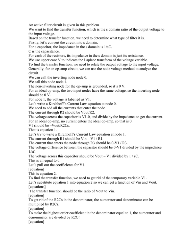
An active filter circuit is given in this problem. We want to find the transfer function, which is the s domain ratio of the output voltage to the input voltage. Based on the transfer function, we need to determine what type of filter it is. Firstly, let’s convert the circuit into s domain. For a capacitor, the impedance in the s domain is 1/sC. C is the capacitance. For each of the resistors, its impedance in the s domain is just its resistance. We use upper case V to indicate the Laplace transform of the voltage variable. To find the transfer function, we need to relate the output voltage to the input voltage. Generally, for an op-amp circuit, we can use the node voltage method to analyze the circuit. We can call the inverting node node 0. We call this node node 1. The non-inverting node for the op-amp is grounded, so it’s 0 V. For an ideal op-amp, the two input nodes have the same voltage, so the inverting node should be 0 V. For node 1, the voltage is labelled as V1. Let’s write a Kirchhoff’s Current Law equation at node 0. We need to add all the currents that enter the node. The current through R2 should be Vout/R2. The voltage across the capacitor is V1-0, and divide by the impedance to get the current. For an ideal op-amp, no current enters the ideal op-amp, so that is 0. V1 should be –Vout/R2Cs. That is equation 1. Let’s try to write a Kirchhoff’s Current Law equation at node 1. The current through R1 should be Vin – V1 / R1. The current that enters the node through R3 should be 0-V1 / R3. The voltage difference between the capacitor should be 0-V1 divided by the impedance 1/sC. The voltage across this capacitor should be Vout – V1 divided by 1 / sC. This is all equal to 0. Let’s pull out the coefficients for V1. [equation] This is equation 2. To find the transfer function, we need to get rid of the temporary variable V1. Let’s substitute equation 1 into equation 2 so we can get a function of Vin and Vout. [equations] The transfer function should be the ratio of Vout to Vin. [equation] To get rid of the R2Cs in the denominator, the numerator and denominator can be multiplied by R2Cs. [equation] To make the highest order coefficient in the denominator equal to 1, the numerator and denominator are divided by R2C². [equation] That is the transfer function for the circuit. From the transfer function, we can tell that this is a bandpass filter. For a bandpass filter, the transfer function can be written as such: [equation]. ω0 is the center frequency and β is the bandwidth of the bandpass filter.
