THE DEVELOPMENT OF WIDE FIELD OF VIEW HYPERSPECTRAL IMAGER
advertisement
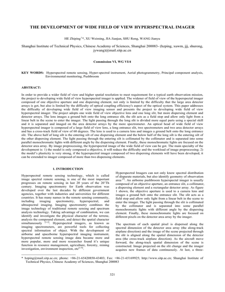
THE DEVELOPMENT OF WIDE FIELD OF VIEW HYPERSPECTRAL IMAGER HE Zhiping 1 *, XU Weiming, JIA Jianjun, SHU Rong, WANG Jianyu Shanghai Institute of Technical Physics, Chinese Academy of Sciences, Shanghai 200083- (hzping, xuwm, jjj, shurong, jywang)@mail.sitp.ac.cn Commission VI, WG VI/4 KEY WORDS: Hyperspectral remote sensing, Hyper-spectral instrument, Aerial photogrammetry, Principal component analysis, Environmental monitoring, Pushbroom ABSTRACT: In order to provide a wider field of view and higher spatial resolution to meet requirement for a typical earth observation mission, the project to developing wide field of view hyperspectral imager is applied. The widener of field of view of the hyperspectal imager composed of one objective aperture and one dispersing element, not only is limited by the difficulty that the large area detector arrays is got, but also is limited by the difficulty of optical coupling efficiency's aspect of the optical system. This paper addresses the difficulty of developing wide field of view imaging sensor and presents the project to developing wide field of view hyperspectral imager. The project adopts one wide field of view objective lens and one long slit, but more dispersing element and detector arrays. The lens images a ground belt onto the long entrance slit, the slit acts as a field stop and allow only light from a linear belt in the scene to enter the imager. The light passing through the long slit is divided more equal parts using a special skill and it is separated and imaged on the area detector arrays by the more spectrometer. An optical head of wide field of view hyperspectral imager is composed of a large field of view lens, a long entrance slit, two spectrometers and two area detector arrays and has a cross-track field of view of 60 degrees. The lens is used to a camera lens and images a ground belt onto the long entrance slit. The above half of long silt is the entering silt of one dispersing element and the below half of the long silt is the entering silt of the other dispersing element. The light passing through the entering silt is collimated by the collimator and is separated into some parallel monochromatic lights with different angle by the dispersing element. Finally, these monochromatic lights are focused on the detector area array. By image preprocessing, the hyperspectral image of the wide field of view can be got. The main specialty of the development is: 1) the model is only composed a objective, it will reduce the difficulty and the workload of image preprocessing; 2) the model’s plasticity is very strong, if the hyperspectral imager composed of two dispersing elements will have been developed, it can be extended to imager composed of more than two dispensing elements. 1. INTRODUCTION Hyperspectral Imagers can not only know spectral distribution of disparate materials, but also identify geometry of observation area [3]. An airborne pushbroom hyperspectal imager is usually composed of an objective aperture, an entrance slit, a collimator, a dispersing element and a rectangular detector array. As figure 1 shown, the objective aperture is used to a camera lens and images a ground belt onto the entrance slit. The slit acts as a field stop and allow only light from a linear belt in the scene to enter the imager. The light passing through the slit is collimated by the collimator and is separated into some parallel monochromatic lights with different angle by the dispersing element. Finally, these monochromatic lights are focused on different pixels on the detector area array by the imager. Hyperspectral remote sensing technology, which is called image spectral remote sensing, is one of the most important progresses on remote sensing in last 20 years of the 20’Th century. Imaging spectrometry for Earth observation was developed over the last decades by different government agencies, together with industries and universities for different countries. It has many names in the remote sensing community, including imaging spectrometry, hyperspectral, and ultraspectral imaging. Imaging spectrometry combines the image technology of traditional remote sensing and spectrum analysis technology. Taking advantage of combination, we can identify and investigate the physical character of the terrene, analysis the compound element, and detect the spatial character simultaneously [1-2]. Hyperspectral imagers, as known as imaging spectrometers, are powerful tools for collecting spectral information of object. With the development of airborne and spaceborne hyperspectral imaging instrument, hyperspectral remote sensing image data became more and more popular, more and more researcher found it’s unique function in resource management, agriculture, forestry, mining investigation, environment inspection, etc[1-9]. The spectrum of each spatial pixel is dispersed along the spectral dimension of the detector area array (the along-track airplane direction) and the image of the scene projected through the slit is aligned along the spatial dimension of the detector area (the cross-track airplane direction). As the aircraft move forward, the along-track spatial dimension of the scene is constructed. Image projected on the slit change and the imager acquires new frames of data continuously. At last, a three- * hzping@mail.sitp.ac.cn; phone: +86-21-65420850-43403; Fax: +86-21-65169925; http://www.sitp.ac.cn; Shanghai Institute of Technical Physics, Chinese Academy of Sciences, Shanghai 200083 321 The International Archives of the Photogrammetry, Remote Sensing and Spatial Information Sciences. Vol. XXXVII. Part B7. Beijing 2008 dimensional image cube with two spatial dimensions and one spectral dimension is acquired. [1] 2. THE PRINCIPLE AND OPTICAL MODEL OF WIDE FIELD OF VIEW HYPERSPECTRAL IMAGING Collimator A Objective A C D H’ O O1 O2 H B B Figure 3: the principle of wide field of view hyperspectral imager Figure 3 is the principle of wide field of view hyperspectral imager. As figure 3 shown, the beam radiated from a ground belt enters in the objective aperture AB and images onto the slit HOH’. The slit acts as a field stop and allow only light from a linear belt in the scene to enter the imager. The light passing through the slit is collimated by the collimator and is separated into some parallel monochromatic lights with different angle by the dispersing element. Finally, these monochromatic lights are focused on different pixels on the detector area array. From the figure 3, it can be got that the F number of the collimator is must less than the F number of the objective so to be sure that the beam passing through the slit can be high efficiency coupled in the dispersing element. The phenomena is especially extrude when the field of view of the imager is widen and it influence Figure 1: scheme of a pushbroom hyperspectal imager [3] Objective aperture Dispersing element Detector Slit Figure 2: The optical head model of a hyperspectral imager collimator Objective grating imager Detector silt An airborne pushbroom hyperspectal imager is usually composed of an objective aperture, an entrance slit, a dispersing element and a rectangular detector array. As figure 2 shown is the optical head model of a pushbroom hyperspectral imager. The widener of field of view of the hyperspectal imager composed of one objective aperture and one dispersing element, not only is limited by the difficulty that the large area detector arrays is got, but also is limited by the difficulty of optical coupling efficiency's aspect of the optical system. In order to provide a wider field of view and higher spatial resolution to meet requirement for a typical earth observation mission, the project to developing wide field of view hyperspectral imager is applied. The airborne hyperspectral imager under development is consisted of an objective lens with wide field of view, a long linear silt which divide up the light radiated from a long linear belt to two parts, two dispersing elements and two detectors arrays. The hyperspectral imager have a cross-track field of view of 60 degree with an 2×2 m GSD(Ground Sample Distance) from a nominal 2 Km flight altitude. The analysis shows that the wide field of view hyperspectral imager doesn’t drop down the spatial resolution. Figure 4: The optical head model of wide field of view hyperspectral imager that the field of view of hyperspectral imager is widen. The sketch map of the project of wide field of view hyperspectral imager is shown on figure 4. The objective aperture is used to a camera lens and images a ground belt onto the long entrance slit. The long slit acts as a field stop and allow only light from a linear belt in the scene to enter the imager. The above half of long silt is the entering silt of one dispersing element and the below half of the long silt is the entering silt of 322 The International Archives of the Photogrammetry, Remote Sensing and Spatial Information Sciences. Vol. XXXVII. Part B7. Beijing 2008 the other dispersing element. The light passing through the entering silt is collimated by the collimator and is separated into some parallel monochromatic lights with different angle by the dispersing element. Finally, these monochromatic lights are focused on the detector area array. By image preprocessing, the hyperspectral image of the wide field of view can be got. 3.2 The long silt of wide field of view hyperspectral imager 3. THE OPTICAL HEAD OF WIDE FIELD OF VIEW HYPERSPECTRAL IMAGER 3.1 The optical head of wide field of view hyperspectral imager Figure 6:the long silt of wide field of view hyperspectral imager The long slit of hyperspectral imager divide up the light radiated from a long linear belt to two parts entering individually into two dispersing elements, its characteristic is to divide up the wide field of view and to make the divided field of view apart spatially, so it is benefit to the layout of the subsequence optical element. As figure 6 shown, the long slit is composed of two corner cube prisms, the two prisms are conglutinated to a element, the inclined planes of the corner cube prisms are respectively coated a linear reflect coating. The project to developing wide field of view hyperspectral imager adopts the model that compose of one wide field of view objective lens and one long slit that divide up the light radiated from a long linear belt to two parts entering individually into two dispersing elements. So, the optical head of hyperspectral imager is composed of an objective aperture, one long silt, two dispersing elements and two detector arrays. The optical head of wide field of view hyperspectral imager is as figure 5. The project of wide field of view hyperspectral imager uses more dispersing elements, and the beam radiated from a ground belt enters in the objective aperture and high efficiency couples in the dispersing element. As figure 5 shown, the long linear ground belt is imaged on two slits by the wide field of view objective lens, the light passing through the silts reflect to two beam by the slits and high efficiency couple into the dispersing elements. 4. THE CALIBRATION FACILITY FOR WIDE FIELD OF VIEW HYPERSPECTRAL IMAGING Object screen large integrating sphere Collimator Slit Dispersing element Detector Optical head of the hyperspectral imager Control signal Computer Collimator with 4 m focal length Monochromato r Imaging data Figure 7: layout of calibration of the wide field of view hyperspectral imager Objective lens Calibration facility for wide field of view hyperspectral imaging was set-up. It meets the requirements for geometric, spectral and radiometric calibration of the development of wide field of view hyperspectral imager. The calibration facility was mostly composed of a collimator, a monochromator, a large integrating sphere, an object screen. Figure 7 is the layout of calibration of the wide field of view hyperspectral imager. Figure 5:the optical head of wide field of view hyperspectral imager The hyperspectral imager under development is an airborne pushbroom-scanning instrument and the primary design performance specification is as follows: Spectral resolution: <5nm Spectral range: 420-900 nm Spectral channels: 124 channels Field of view: 60 degrees Spatial angular resolution: 1 mrad As figure 7 shown, signals from two sides can alternatively be sent to the optical head of the hyperspectral imager under investigation. From one side, the spatial and spectral will alternatively be done. The spatial calibration is performed using the collimator and slits of different size in the object screen and the spectral calibration is performed using the collimator and the monochromator. Form the other side, the radiometric calibration will be done using the inregrating sphere. 323 The International Archives of the Photogrammetry, Remote Sensing and Spatial Information Sciences. Vol. XXXVII. Part B7. Beijing 2008 11. Qingxi Tong, Lanfen Zheng, Yongqi Xue, “Development and application of hyperspectral remote sensing in China”, SPIE, Vol. 3502, p. 2-9, 1998 12. Hui Shao, Yongqi Xue, Jianyu Wang, “Development of Chinese pushbroom hyperspectral imager (PHI)”, SPIE, Vol. 3505, p. 108-115, 1998 13. Daniel R. Schlapfer, Johannes W. Kaiser, Jason Brazile, et al. “Calibration concept for potential optical aberrations of the APEX pushbroom imaging spectrometer”, SPIE, Vol. 5234, p. 221-231, 2004 14. Michael E. Schaepman, Klaus I. Itten, Daniel R. Schlaepfer, et al. “APEX: current status of the airborne dispersive pushbroom imaging spectrometer”, SPIE, Vol. 5234, p. 202-210, 2004 5. CONCLUSION The airborne hyperspectral imager under development is consisted of a objective lens with wide field of view, a long linear silt which divide up the light radiated from a long linear belt to two parts, two dispersing elements and two detectors arrays, it provides a wider field of view and higher spatial resolution to meet requirement for a typical earth observation mission. The hyperspectral imager have a cross-track field of view of 60 degree with an 2×2 m GSD(Ground Sample Distance) from a nominal 2 Km flight altitude. The main specialty of the development is: 1) the model is only composed a objective, it will reduce the difficulty and the workload of image preprocessing; 2) the model’s plasticity is very strong, if the hyperspectral imager composed of two dispersing elements will have been developed, it can be extended to imager composed of more than two dispensing elements. ACKNOWLEDGEMENTS This work is supported by the National High Technology Research and Development Program of China (863 Program). The authors would like to acknowledge the many colleagues, who had made the work so fascinating, challenging and rewarding. REFERENCES 1. Jianyu Wang, Rong Shu, Yongqi Xue, “The development of Chinese hyperspectral remote sensing technology ”, SPIE, Vol. 5640, p. 358-26, 2005 2. Zhiping He, Kangmei Fang, Liyun Pang, et al. “Field-putting technique of wide-field hyperspectral imager”, SPIE, Vol. 5634, p. 775-781, 2005 3. J. Nieke, H. Schwqrzer, A. Neumann et al. “Imaging spaceborne and airborne sensor systems in the beginning of the next century”, SPIE, Vol. 3221, p. 22-26, 1997 4. Birk, Ron J., McCord, T.B, “Airborne Hyperspectral Sensor Systems”, IEEE Aerospace and Electronic Systems Magazine, Vol. 9, No. 10, p. 26-33, 1994 5. Staenz, Karl, “A Decade of Imaging Spectrometry in Canada”, Canadian Journal of Remote Sensing, Vol.18, No.4, 187-197, 1992 6. Ron Buckingham, Karl Staenz, Allan Hollinger, “Review of Canadian Airborne and Space Activities in Hyperspectral Remote Sensing”, Canadian Aeronautics and Space Journal, Vol. 48, No. 1, p. 115-121, 2002 7. Curtiss o. Davis, Jeffrey Bowles, Robert A. Leathers, Dan Korwan, et al., “Ocean PHILLS hyperspectral imager: design, characterization, and calibration”, OPTICS EXPRESS, Vol. 10, No. 4, p. 210-221, 2002 8. SHEN Ming-Ming, Wang Jian-Yu, “Airborne Imaging Spectrometer System”, Journal of Infrared and Millimeter Waves, Vol. 17, No. 1, p. 7-12, 1998 9. Shao Hui, Wang Jianyu, Xue Yongqi, “Key Technology of pushbroom Hyperspectral Imager (PHI)”, JOURNAL OF REMOTE SENSING, Vol. 2, No. 4, p. 251-254, 1998 10. Yuzhong Liu, Jie Zhang, Yongqi Xue, et al. “Advance in marine technique and application research of airborne hyperspectral remote sensing in China”, SPIE, Vol. 4897, p. 4450, 2003 324
