A COMPARATIVE STUDY OF IMPRESSION TAKING PROCEDURES IN DENTISTRY
advertisement
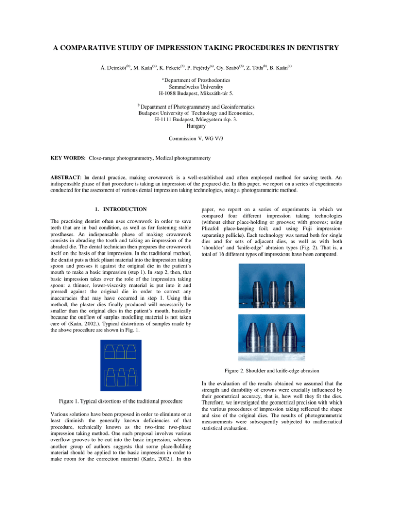
A COMPARATIVE STUDY OF IMPRESSION TAKING PROCEDURES IN DENTISTRY Á. Detrek i(b), M. Kaán(a), K. Fekete(b), P. Fejérdy(a), Gy. Szabó(b), Z. Tóth(b), B. Kaán(a) a Department of Prosthodontics Semmelweiss University H-1088 Budapest, Mikszáth-tér 5. b Department of Photogrammetry and Geoinformatics Budapest University of Technology and Economics, H-1111 Budapest, M egyetem rkp. 3. Hungary Commission V, WG V/3 KEY WORDS: Close-range photogrammetry, Medical photogrammerty ABSTRACT: In dental practice, making crownwork is a well-established and often employed method for saving teeth. An indispensable phase of that procedure is taking an impression of the prepared die. In this paper, we report on a series of experiments conducted for the assessment of various dental impression taking technologies, using a photogrammetric method. 1. INTRODUCTION The practising dentist often uses crownwork in order to save teeth that are in bad condition, as well as for fastening stable prostheses. An indispensable phase of making crownwork consists in abrading the tooth and taking an impression of the abraded die. The dental technician then prepares the crownwork itself on the basis of that impression. In the traditional method, the dentist puts a thick pliant material into the impression taking spoon and presses it against the original die in the patient’s mouth to make a basic impression (step 1). In step 2, then, that basic impression takes over the role of the impression taking spoon: a thinner, lower-viscosity material is put into it and pressed against the original die in order to correct any inaccuracies that may have occurred in step 1. Using this method, the plaster dies finally produced will necessarily be smaller than the original dies in the patient’s mouth, basically because the outflow of surplus modelling material is not taken care of (Kaán, 2002.). Typical distortions of samples made by the above procedure are shown in Fig. 1. paper, we report on a series of experiments in which we compared four different impression taking technologies (without either place-holding or grooves; with grooves; using Plicafol place-keeping foil; and using Fuji impressionseparating pellicle). Each technology was tested both for single dies and for sets of adjacent dies, as well as with both ‘shoulder’ and ‘knife-edge’ abrasion types (Fig. 2). That is, a total of 16 different types of impressions have been compared. Figure 2. Shoulder and knife-edge abrasion Figure 1. Typical distortions of the traditional procedure Various solutions have been proposed in order to eliminate or at least diminish the generally known deficiencies of that procedure, technically known as the two-time two-phase impression taking method. One such proposal involves various overflow grooves to be cut into the basic impression, whereas another group of authors suggests that some place-holding material should be applied to the basic impression in order to make room for the correction material (Kaán, 2002.). In this In the evaluation of the results obtained we assumed that the strength and durability of crowns were crucially influenced by their geometrical accuracy, that is, how well they fit the dies. Therefore, we investigated the geometrical precision with which the various procedures of impression taking reflected the shape and size of the original dies. The results of photogrammetric measurements were subsequently subjected to mathematical statistical evaluation. 2. THE METHOD OF INVESTIGATION 2.1 Producing the sample dies For the purposes of this investigation, we have devised and manufactured an instrument to produce laboratory conditions close to in vivo conditions and to standardize the impression taking procedure in vitro. The instrument consists of a platen, a part corresponding to the dental impression taking spoon, as well as a pair of rails with a sliding surface to keep the movement of the spoon onto the platen identical across instances (Fig. 3). three adjacent knife edge dies, three adjacent shoulder dies), with all four techniques. Thus, a total of 16 different models have been made; a 12-piece series was then made of each model. The impressions were then cast with Kromotypo 4 hard plaster; good quality setting was facilitated by using a vacuum mixer and a vibrator. The next task can be briefly summarized as follows. The various procedures will be assessed in terms of statistical correspondence between the set of hard plaster models and the original steel dies. The impression taking procedure for which the statistically demonstrable difference between the original shape and the model produced is the smallest will turn out to be the best. 2.2 Determining the geometrical data of the model pieces Figure 3. The sampling instrument One of the most important features of an instrument of the kind shown above is its reproductive capacity, meaning in this case the precision with which it can be reset exactly to the same position while producing two different samples. Due to appropriately strict assembly and well-chosen production tolerance, as confirmed by an independent expert investigation (Budapest University of Technology and Economics, Department of Precision Mechanics and Optics), the zero position resetting accuracy of the instrument is 0,004 mm. A phase of the calibration of the instrument is shown in Fig. 4. For determining the parameters of the model pieces, we employed the method of photogrammetry; i.e., the data were not directly measured on the objects concerned but on photographs made of them. In particular, we obtained coordinates by a method now generally used in close-range photogrammetric tasks, an instance of which is the present task, i.e., by what is known as multi-viewpoint photography. For the calculations, we used a DLT (direct linear transformation) program developed at the Department of Photogrammetry and Geoinformatics of the Budapest University of Technology and Economics. The program and its testing procedure were reported on elsewhere (Detrek i 2002). In order to perform photogrammetric tasks, it is necessary that the pictures exhibit control points: it is with the help of these that the spatial position of our pictures is determined. It is a usual method in close-range photogrammetry that the spatial position of these points is not determined task by task; rather, a ‘test-field’ applicable to a number of tasks is prepared beforehand. This was done in the present case, too. The dies were put into a test-field developed by the Department of Photogrammetry and Geoinformatics of the Budapest University of Technology and Economics. The geometrical characteristics of the test-field were determined with a Zeiss Opton 3D coordinate-measuring instrument. That instrument shows the coordinates of points with a tenth of a micron accuracy and with a mean square error less than a micron. The calibration of the test field is shown in Fig. 5. Figure 4. The truing of the sampling instrument The platen of the instrument shown in Figs. 3 and 4 accommodates one to three stainless steel dies that imitate the original abraded dies. These steel dies were made in a regular geometrical shape to facilitate comparison and, using a surface grinder, their surface roughness was made similar to that of abraded teeth. An important component of standardization was that the individual samples, produced one after the other, should be pressed against the platen with the same force. This was achieved by imitating the average human pressure of 20 N by a 2 kg weight piece placed on top of the spoon. With this apparatus, impressions were made in four arrangements (single knife edge die, single shoulder die, Figure 5. The calibration of the test field with a Zeiss 3D coordinate-measuring instrument Four samples were put into the test-field at a time, corresponding ones always to the same place, before the photographs were taken. With this solution, we made sure that results were not distorted by differences in geometrical arrangement. The photographs were taken with a Nikon D1 2000X1320 pixel digital camera, from the same four viewpoints in each case. One of the pictures used for subsequent calculations is shown in Fig. 6. parameter at hand. In determining that technological value, we used error filtering based on statistical tests where required; then the arithmetical mean of the filtered values was accepted as the final value. The parameters of the metal dies, i.e., the technological values of the various methods of impression taking, were compared with respect to bottom diameter, middle diameter, height, overall width, and, for shoulder arrangements, shoulder diameter. Numerical values of the results are shown in Figs. 8, 9, 10, and 11. Adding all differences measured in the various test dimensions, we get a single value, call it total error, that characterises each procedure investigated. This is shown, along with typical distortions found with plain dies (meaning ones without either place-holding or grooves), in Figs. 12 and 13. Average values of bottom and middle diameters of knifeedge model dies compared to those of metal dies for the four impression taking methods (in mm) Figure 6. A picture used for subsequent calculations The pictorial coordinates were measured using a PC, with the help of software packages of a sub-pixel accuracy level. 3. RESULTS AND DISCUSSION 3.1 Determining the geometrical parameters The objects symbolizing the original dies were regular geometrical solids; in particular, they were composed of a truncated cone sitting on a cylinder. In the case of the ‘shoulder’ arrangements, the latter was mounted on another cylinder of a longer radius. The reason for this was that fewer parameters were required for a geometrical comparison of the original object and the copy than would be the case with irregular shapes. The parameters used numbered ten on average, across the four different methods of impression taking; for stand-alone dies that number was lower, whereas for sets of dies, it was higher. These parameters represented the main dimensions of the given solid like bottom diameter, middle diameter (i.e., diameter of the circle where the cylinder and the truncated cone meet), height of die, distance between dies, overall width of dies, diameter of circular shoulder, etc. Since photogrammetry is a method of determining spatial coordinates of points, the parameters were distances between pairs of points in all cases. For the identification of those points, we milled marks on the metal dies, faithfully mapped on each plaster die. Fig. 7 shows the parameters selected. Figure 8.a Bottom and middle diameters Average values of bottom and middle diameters of shoulder model dies compared to those of metal dies for the four impression taking methods (in mm) Figure 8.b Bottom and middle diameters Average values of height of knife-edge model dies compared to those of metal dies for the four impression taking methods (in mm Figure 7. Parameters measured in the experiment With the application of that method, we got a twelve-element sample for each selected quantity; the value composed of those values was then accepted as the technological value of the Figure 9.a Height of dies Figure 10.b Overall width Average values of height of shoulder model dies compared to those of metal dies for the four impression taking methods (in mm) Average values of shoulder width of model dies for the four impression taking methods (in mm) Figure 9.b Height of dies Average values of overall width of knife-edge model dies compared to those of metal dies for the four impression taking methods (in mm) Figure 11. Shoulder width Average total error for the four impression taking methods with knife-edge model dies Figure 10.a Overall width Average values of overall width of shoulder model dies compared to those of metal dies for the four impression taking methods (in mm) Figure 12. Knife-edge total error Average total error for the four impression taking methods with shoulder model dies Engineering and Remote Sensing, Vol. 44, no. 9, pp. 1191– 1196. 2. Detreköi, Á. – Fekete, K. – Tóth, Z. – Alhusain, O. – Juhász, A. – Stuber, I. – Rakusz, Á. (2002): Representing the Human Vascular System with the Use of X-ray Pictures, International Archives of Photogrammetry and Remote Sensing Vol. XXXII. Part B5 Comission V, Corfu, Greece, pp. 247–249. 3. Fekete, K. (1996): Developing the surface model of human gums, International Archives of Photogrammetry and Remote Sensing Vol. XXXI Part B5, Vienna, pp. 160–166. Figure 13. Shoulder total error 3.2 Conclusions The analysis of those technological parameters yielded the following geometrical conclusions for shoulder and knife edge arrangements: 1. The number of dies, that is, whether several adjacent dies were tested or just one, did not influence the distortion tendencies per die in any of the impression taking procedures. 2. The model dies made without preparation and those made with grooves were significantly taller than the original object, whereas those made with place holders were practically identical in height with the original die . 3. The bottom circles of the models and their middle circles showed significant differences in diameter for each method, that is, the cylindrical parts of all model dies were getting narrower towards the top. The extent of narrowing was the lowest for impressions made with a Fuji spearating foil and with a Plicafol foil. The most pronounced narrowing, i.e., a significantly shorter middle diameter than in all the other cases, was found for the impressions made without any place holding or grooves. 4. The total width of dies was diminished in all models made by any of the methods; they did so the most drastically for the unprepared and for the grooved impressions. 5. In the case of shoulder dies, the diameter of shoulders also diminished; the least so in cases where some place holder was used. 4. SUMMARY In this series of experiments, we have compared four different dental impression taking technologies using geometrical data obtained by a photogrammetrical method. From the analysis of those data, the following points became clear: Impressions taken without preparation and those prepared with grooves are unfaithful to the original: the model dies we got from casting those impressions were taller and thinner than the original dies. This suggests that grooves do not sufficiently allow for the outflow of surplus correction material.The shape and size of the original metal die was faithfully reproduced by the use of impressions made with place holding foils; but no significant difference was found in accuracy between the two such technologies involved in the experiment. 5. REFERENCES 1. Bopp, H. – Krauss, H. (1978): An orientation and calibration method for non topographic applications, Photogrammetric 4. Kaán, B. – Fekete, K. – Somogyi, E. – Kaán, M. – Fejérdy, P. (2002): An examination of the modelling ability of two-time two-phase silicon impression taking procedures, with a specially designed tool and method, Hungarian Dental Association Árkövy Conference Word Dental Congress, Vienna, p. 39. 5. Krauss, K. (1998): Fotogrammetria (university textbook), Tetria Kiadó, Budapest.
