PRODUCTION AND PRECISION ANALYSIS OF A DIGITAL ORTOPHOTO FROM... SCALED AIRPHOTO AS A GIS COVERAGE
advertisement
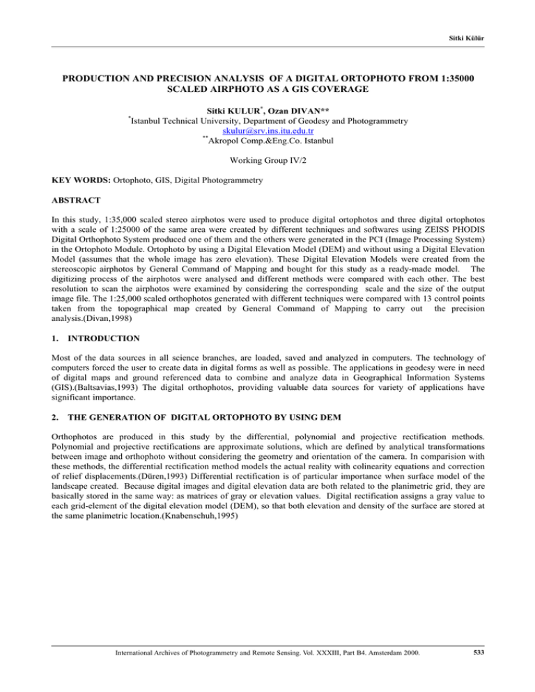
Sitki Külür PRODUCTION AND PRECISION ANALYSIS OF A DIGITAL ORTOPHOTO FROM 1:35000 SCALED AIRPHOTO AS A GIS COVERAGE Sitki KULUR*, Ozan DIVAN** Istanbul Technical University, Department of Geodesy and Photogrammetry skulur@srv.ins.itu.edu.tr ** Akropol Comp.&Eng.Co. Istanbul * Working Group IV/2 KEY WORDS: Ortophoto, GIS, Digital Photogrammetry ABSTRACT In this study, 1:35,000 scaled stereo airphotos were used to produce digital ortophotos and three digital ortophotos with a scale of 1:25000 of the same area were created by different techniques and softwares using ZEISS PHODIS Digital Orthophoto System produced one of them and the others were generated in the PCI (Image Processing System) in the Ortophoto Module. Ortophoto by using a Digital Elevation Model (DEM) and without using a Digital Elevation Model (assumes that the whole image has zero elevation). These Digital Elevation Models were created from the stereoscopic airphotos by General Command of Mapping and bought for this study as a ready-made model. The digitizing process of the airphotos were analysed and different methods were compared with each other. The best resolution to scan the airphotos were examined by considering the corresponding scale and the size of the output image file. The 1:25,000 scaled orthophotos generated with different techniques were compared with 13 control points taken from the topographical map created by General Command of Mapping to carry out the precision analysis.(Divan,1998) 1. INTRODUCTION Most of the data sources in all science branches, are loaded, saved and analyzed in computers. The technology of computers forced the user to create data in digital forms as well as possible. The applications in geodesy were in need of digital maps and ground referenced data to combine and analyze data in Geographical Information Systems (GIS).(Baltsavias,1993) The digital orthophotos, providing valuable data sources for variety of applications have significant importance. 2. THE GENERATION OF DIGITAL ORTOPHOTO BY USING DEM Orthophotos are produced in this study by the differential, polynomial and projective rectification methods. Polynomial and projective rectifications are approximate solutions, which are defined by analytical transformations between image and orthophoto without considering the geometry and orientation of the camera. In comparision with these methods, the differential rectification method models the actual reality with colinearity equations and correction of relief displacements.(Düren,1993) Differential rectification is of particular importance when surface model of the landscape created. Because digital images and digital elevation data are both related to the planimetric grid, they are basically stored in the same way: as matrices of gray or elevation values. Digital rectification assigns a gray value to each grid-element of the digital elevation model (DEM), so that both elevation and density of the surface are stored at the same planimetric location.(Knabenschuh,1995) International Archives of Photogrammetry and Remote Sensing. Vol. XXXIII, Part B4. Amsterdam 2000. 533 Sitki Külür Ýmage Plane Projection Center Image Plane Projection Center Photo Direction Terrain Terrain Projection Distortion Terrain Elevation Distortion Figure:1 Distorsions due Projektion and Terrain Elevation ( Lüken,1995) The steps followed during the generation of two orthophotos in the PCI software can be summarized as follows: a) Scanning of the airphoto b) The data format of the scanned airphoto is converted to another file format, which can be read by PCI (i.e. TIFFRD, IMAGERD, SUNREAD, LINK) c) The collection of ground control points: The user should decide which method to use for the image correction; image to image, map to image, coordinates to image or vector to image. The reference ground control points are collected to match the raw image and the map, in order to set UTM coordinates and the elevation parameter to the raw image. d) The principle point & the size of the airphoto: The principle point, length & width of the airphoto for the interior orientation can be obtained from the image window on the screen, by using PPOINT. e) The modeling of the airphoto camera: The position and the orientation of the camera are the parameters to be used in the rectification of the image by ORTHO program. One of the orthophotos was generated without Digital Elevation Model (DEM), assuming that each pixel of the DEM is zero. (Fig:2) The other orthophoto was created by using elevation data generated by General Command of Mapping was imported to Arc/Info as a point coverage. The topology of the coverage was built and the projection was defined as International Hayford 1909 Ellipsoid in second. 534 International Archives of Photogrammetry and Remote Sensing. Vol. XXXIII, Part B4. Amsterdam 2000. Sitki Külür Figure: 2 Ortophoto of the Region The continuity of the layer was provided by the interpolation method for the 20m-cell size. The output of the interpolation was a raster image, which was clipped from the boundary coordinates. This point coverage in Arc/info was converted to elevation contours with 20m interval in order to process data in PCI software. The elevation contours in Arc/Info vector format were converted into PCI vector format and coded in a raster format. Interpolating contour lines in raster format, which is then to be used for the generation of the orthophoto, created the DEM. 3. STEREOSCOPIC APPLICATION Photogrammetric Image Processing System (PHODIS) was used for the stereoscopic application of the airphotos. The selection of the Wild model of the camera obtains the information of principal point coordinates and the amount of distortion from the file, which was previously prepared by ZEISS. The name of the file, pixel size of the image, total amount of pixels, number of bands, the name of the image were loaded automatically to the system as digital image information. The name of the file, upper right and lower left coordinates, grid points and the frequency of grid points were defined on the empty DEM screen window. The name of the orthophoto file, scale, the method of rectification, the number of bands of the image, upper right and lower left coordinates, the pixel size of the output image or the ground resolution were defined for the orthophoto. After the process of the interior and exterior orientation were completed, the DEM was checked over to completely cover the image, and then rectified. In this software, TopoSURF module was used to generate DEM from the interior and exterior oriented stereoscopic images.(Phodis,1993) International Archives of Photogrammetry and Remote Sensing. Vol. XXXIII, Part B4. Amsterdam 2000. 535 Sitki Külür 4. CONCLUSION AND DISCUSSION The orthophotos generated from different softwares (PCI and Phodis), with different techniques, were compared for the accuracy. In each orthophoto, the coordinates of the common 13 reference points were taken to find out the orthophoto with the best accuracy. The error of the coordinates measured from 1:25000 scaled topographical map was assumed to be zero. The mean square error for the orthophotos was computed by matching the locations of the points on the orthophotos and the topographical map. As a result, the mean square error of the orthophoto produced by the assumption that the whole image has zero elevation was found to be 109m, the one generated from the stereo airphotos was observed to be 36m, and for the last one, generated by using DEM was found to be 13m. (Fig:3) For the precision of the orthophotos generated by using DEM, the accuracy of DEM should also be taken into account. (Schiewe,1994) Figure:3 Perspective view of an Ortophoto The flight height of the airplane while taking 1:35000 scaled airphotos was determined to be 5500m. The correctness of the DEM with the parameters; 1:25000 scaled orthophoto, the longest distance of 16m. between the projection center and the object point, 0,2 mm position error of the DEM was 10m. The best orthophoto, which has the minimum mean square error was produced by applying 20m DEM. The other orthophoto, which has 36m mean square error, was generated from 30m DEM. It is observed that the higher the precision of the DEM, the higher the accuracy of the orthophoto generated. The orthophoto, produced from the stereoscopic images were discovered to have the highest error. The height flight distance and a positional error of more than 10m can explain the reason. As a result, it can be concluded that by using differential rectification method, in comparison with the other techniques the most accurate orthophoto was produced. REFERENCES 1. BALTSAVIAS, E. P., 1993, Integration of Ortho-Images in GIS, Photogrammetric Week, Herbert Wichmann Verlag, Karlsruhe. 2. DIVAN, O. 1998, Generation and Use of Digital Orthophoto, MSc Thesis, TU Istanbul 3. DÜREN, U., 1993, Digital Orthophoto Generation, First Course in Digital Photogrammetry, Institut für Photogrammetrie der Universitaet Bonn and Landvermessungsamt Nordrhein Westfalen, Bonn. 536 International Archives of Photogrammetry and Remote Sensing. Vol. XXXIII, Part B4. Amsterdam 2000. Sitki Külür 4. KNABENSCHUH, M., 1995, Generation and Use of Digital Orthophotos, Second Course on Digital Photogrammetry, Bonn. 5. LÜKEN, C., 1995, Ortho Iages in GIS, International Seminar for GIS in ODTU, Ankara. 6. PHODIS Operation Instructions, 1993, Photogrammetric Image Processing System Manuel, Carl Zeiss, Oberkochen. 7. SCHIEWE, J., 1994, Digitale Orthobilder als Datenquelle für Geographische Informationssysteme, Wichmann, Karlsruhe. International Archives of Photogrammetry and Remote Sensing. Vol. XXXIII, Part B4. Amsterdam 2000. 537
