PHOTOGRAMMETRIC CONTROL OF LARGE METALLWORK ... Jozef ternansky, Lubomlr Salkovic
advertisement
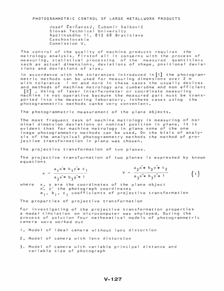
PHOTOGRAMMETRIC CONTROL OF LARGE METALLWORK PRODUCTS Jozef ternansky, Lubomlr Salkovic Slovak Technical University Radlinskeho 11,81368 Bratislava Czechoslovakia Commission V~ The control of the qual ity of machine products requires the metrology analysis. Firstof all it conserns with the process of measuring, statistical processing of the measured quantitiens sach as actual dimensions, deviations of shape, positional deviations and deviations of size. In accordance with the tolerances introduced in[l] the photogrammetric methods can be used for measuring dimensions over 2 m wi th tolerance 1 mm and more In these cases the usually devices and methods of machine metrology are cumbers6me and non efficient [2] • Using of laser interferometer or coordinate measuring machine is not operative because the measured part must be transported into the measuring laboratory~ Inthese cases using the photogrammetric methods canbe very convenient. The photogrammetric measurement of the plane objects. The most frequent task of machine metrology is measuring of nominal dimension deviations or nominal position in plane. It is evident that for machine metrology in plane some of the one image photogrammetry methods can be used. On the bisis of analysis of the analytical photogrammetry methods the method of projective transformation in plane was chosen e The projective transformation of two planes. The projective transformation of two planes equations is expressed by known a 2 x' + b 2 y'+ c 2 y x where a 3x'+ b y'+ 1 3 x, yare the coordinates of the plane object x", y the ph 0 tog rap h coo r din ate s a'l ' b., c. coefficients of projective transformation I I I The properties of projective transformation For investigating of the projective transformation properties a model simulation on microcomputer was employed. During the process of solution four mathematical models of photogrammetric camera vJere v-torked out 18 Model of ideal camera without lens distortion 2. Model of camera with lens distortion 3. Model of camera with variable principal distance and variable size of photograph V-127 4e Model of camera with variable parameters of exterior orientation. By means of the models mentioned above the influence of lens distortion and the interior and exterior orientation parameters on the changes of the plane object coordinates were investigated. The layout of control and detail points created regular raster. The results of mathematical model solution can ce sumarized as follows The focal length directly determines the accuracy of photogrammetryc measurement there fore a scale must be selected inthe way which enables a maximal exploitation of the photograph size& The control and detail points have to lie in a plane. Lens distortion expresses the ful 1 error of plane coordinates, therefore it must be compensated. The parameters of exterior orientation cause the changes of scale therefore it is necessary to minimize the distance of photography and the numerical values of exterior orientation 8 From the fundamental properties of projective transformation there results an important plane condition of object. In the opposite case the projective relation is deformed according to Fig. 1 & The photograph coordinates x~ yl a their changes by the formulas on Fig" 1 will I I Id I I I I I IT Lld P Fig a le Deformation of projective relation V ... 128 show presence Ad Ax ::: ........... d I where d Ad x , I Ad y Ay:: i I ( 2) d is distance of photography de ta i 1 point towards plane i s deviations of a For distance of photography 3.3 m and x': y'::; 60 mm it wi 11 maximum of deviations Ad from plane about 0.1 mm. be Besides the facts mentioned above the accuracy of photogrammetric measurement is influenced by other factors e Other accuracy factors of photogrammetric measurement in plane The accuracy resulting of photogrammetric measurement is enced by influ- - primary accuracy of photograph coordinates - accuracy of control - temperature points influence The accuracy of photogranh coordinates is primary; This one and the scale determinate the accuracy of the plane coordinates and in this way the size of a machine part. By means of precise comparators we can measure the photograph coordinates with the accuracy within 1 - 2 ume The accuracy of control points is derived from a requjrement not to lower the accuracy of photograph coordinates. From this requirement there results the accuracy of control points within 0.05 - 0.1 mm. This very high accuracy of control points can be reached only by measurement on coordinate machine tool. The temperature influence on measurement of large machine parts is considerable. For example the temperature change abont lOC cauSes a deviation in diameter of 3 500 mm about 0.05 mm. The photogrammetric measurement of large machine part Projective transformation method with regard to mentioned factors of ohotogrammetric measurement accuracy was appl ied in control of partially worked out machine part with diameter about 3 500 mm /Fig. 2./ The photography was carried out by a terrestrial camera UMK 10/1318, with focal length f 99.67 from a distance about 3.3 m. The camera axis was approximately perpendicular to the machIne part and passed approximately through its center. The scale reached the value about 1 : 33& In the front of the machine part four pairs of contro] points and two levelling rods were placed. The coordinates of control points were measured by coordinate machine tool with accuracy characterized by standard error V .. 129 m ::0.02 mm x,y x y Fig.2. Control and detai 1 points placed on machine part The air temperature in the machine hall was about 20 o C. For the numerical control of photogrammetric measurement the invar levell ing rods were placed in a plane of control points. The detail points were represented by the worked corners of the machine part /Fig. 2/. They served for the determination of the machine part shape and were photogrammetrical ly measured directly. The photograph coordinates of control points, control lenghts on levelling rods and detail points - work corners of the machine part were measured by precise comparator Komes 3030 - Zeiss Jena in several series, The achieved accuracy of comparator measurement is shown in the Table 1. The accuracy of comparator measurement on control is characterized by standard errors m ,=: X V ... 130 targeted points The accuracy of comparator measurement on detail points Iworked cornersl is characterized by these standard errors mx' = 4.4 fm For the photograph distances measured on levelling rods we achieved these standard errors The purpose of photogrammetric measurement was the determination of the actual plane coordinates of the corners of the machine part IFig~2.1 with regard to its projected values o The projected coordinates of the corners were computed in coordinate system X Y eThe photogrammetric comparator measurement was carried oSt ~~ coordinate system XY being identical with coordinate sys~~ tem of machine tool. Transformation of coordinates between these two coordinate systems was real ized by Helmert transformat ion equations_ The parameters of projective transformation, the coeficients of the equations III were calculated as arithmetic mean from independent combinations of control points. The deviations after the mentioned projective transformation on control points achieved the values which are summarized in Table 2. The residual errors after projective transformation can be expressed by standard error mx,y 0.055 mm = Bya comparison of the control lenghts of levelling rods being placed in direction of coordinate system X and Y we obtained the following diferences : Photograph Nr. 2 Photograph Nr. 3 0.10, 0.02,0.09, 0.24 mm 0.17,0.05,0.,22 mm On the basis of the photogrammetric comparator measurement and data processing of the three photographs we acquired the statistical material for judgement of obtained photogrammetric measurement accuracy of the plane machine part. The accuracy was ~xpressed as the standard errors of plane coordinates Conclusion The example discussed in this paper indicates that the photogrammetric method of projective transformation fogether with· photograph measurement on precise comparator is suitable forthe determination of shape large of machine products with accuracy within Oel - 0 0 2 mm. V .. 131 Accuracy of comparator coordinates Photograph Points Nr & mx m y [flm] [jJ m ] 2.l 1. 6 2~ 5 2.9 3.4 4.6 3.8 4.3 4.4 4.5 4.4 02 Control 03 Leveling 02 rods 03 De ta i 1 02 03 x, Deviations Control y on control Table 1 2" 1 points Table 2 Deviations on control point x points y [mm] [mm] 21 0~08 o 11 26 o~ 03 o 06 o • 02 22 0 11 08 12 oe 03 oe 0 1 o 07 15 0.06 0,,08 24 0" 0 2 0,04 16 e 01 0,,07 0 08 0,,04 t. 11 ! References 014420 [1) tSN [2] ~rma,J .. : Contemporary appl ication terrestrial Uniform System of Tolerances in Czechoslovakia and close range photogrammetry, Supplement of GaKO, SNTL Prague, 1986 V ... 132

![MA1S11 (Timoney) Tutorial/Exercise sheet 1 [due Monday October 1, 2012] 1. 5](http://s2.studylib.net/store/data/010731543_1-3a439a738207ec78ae87153ce5a02deb-300x300.png)