Engineer To Engineer Note EE-134
advertisement

Engineer To Engineer Note
EE-134
Technical Notes on using Analog Devices’ DSP components and development tools
Phone: (800) ANALOG-D, FAX: (781) 461-3010, EMAIL: dsp.support@analog.com, FTP: ftp.analog.com, WEB: www.analog.com/dsp
Copyright 2001, Analog Devices, Inc. All rights reserved. Analog Devices assumes no responsibility for customer product design or the use or application of customers’ products or for
any infringements of patents or rights of others which may result from Analog Devices assistance. All trademarks and logos are property of their respective holders. Information
furnished by Analog Devices Applications and Development Tools Engineers is believed to be accurate and reliable, however no responsibility is assumed by Analog Devices regarding
the technical accuracy of the content provided in all Analog Devices’ Engineer-to-Engineer Notes.
Name
Writing C Compatible Assembly
Code Interrupt Handlers for
the SHARC Family
Kevin C. Kreitzer
last modified 05/10/2001
Introduction
Very often, DSP programs will consist of a mix
of C code and assembly code. The assembly
code is typically used for time critical routines.
Interrupt Service Routines (ISRs) can be some
of the most time critical elements of the program
and, as such, often need to be coded in
assembly. This EE-note describes how to write
C-compatible assembly code interrupt handlers
for the SHARC family.
C Interrupt Handlers
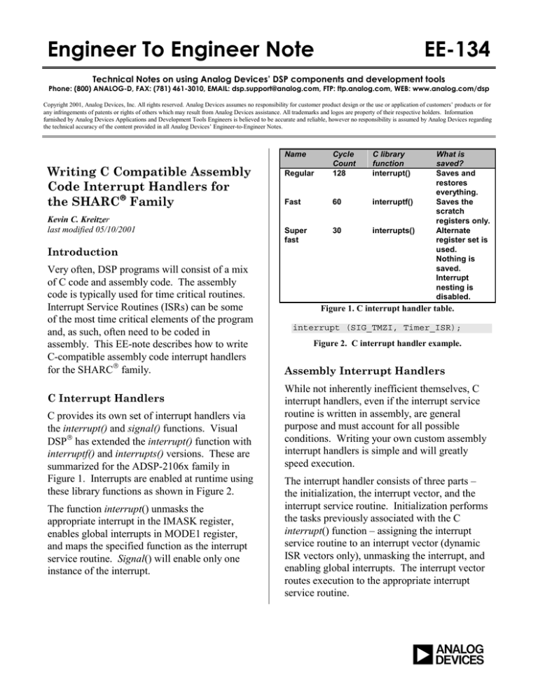
C provides its own set of interrupt handlers via
the interrupt() and signal() functions. Visual
DSP has extended the interrupt() function with
interruptf() and interrupts() versions. These are
summarized for the ADSP-2106x family in
Figure 1. Interrupts are enabled at runtime using
these library functions as shown in Figure 2.
The function interrupt() unmasks the
appropriate interrupt in the IMASK register,
enables global interrupts in MODE1 register,
and maps the specified function as the interrupt
service routine. Signal() will enable only one
instance of the interrupt.
Regular
Cycle
Count
128
C library
function
interrupt()
Fast
60
interruptf()
Super
fast
30
interrupts()
What is
saved?
Saves and
restores
everything.
Saves the
scratch
registers only.
Alternate
register set is
used.
Nothing is
saved.
Interrupt
nesting is
disabled.
Figure 1. C interrupt handler table.
interrupt (SIG_TMZI, Timer_ISR);
Figure 2. C interrupt handler example.
Assembly Interrupt Handlers
While not inherently inefficient themselves, C
interrupt handlers, even if the interrupt service
routine is written in assembly, are general
purpose and must account for all possible
conditions. Writing your own custom assembly
interrupt handlers is simple and will greatly
speed execution.
The interrupt handler consists of three parts –
the initialization, the interrupt vector, and the
interrupt service routine. Initialization performs
the tasks previously associated with the C
interrupt() function – assigning the interrupt
service routine to an interrupt vector (dynamic
ISR vectors only), unmasking the interrupt, and
enabling global interrupts. The interrupt vector
routes execution to the appropriate interrupt
service routine.
a
Interrupt Service Routine
Essential to the proper execution of an interrupt
service routine is a thorough understanding of
the context switch. The context switch must do
two things. The first task is to preserve the state
of the processor for a seamless return to the
main code execution. The second is to put the
processor into a known state in which the
interrupt service routine may properly operate.
There are no scratch registers reserved by C for
use in interrupts. Therefore, all registers used
in an interrupt service routine must be
preserved. One register needing preservation
that may not be obvious is the arithmetic status
or ASTAT register. Any operations in the
interrupt service routine that modify the flags
will affect this register. The ASTAT register is
pushed onto the hardware status stack implicitly
for external interrupts (IRQs), vector interrupts,
and timer interrupts. For all other interrupts, it
must be pushed and popped explicitly.
Once the MODE1 register is pushed, the
processor can then be set to a known state for
the interrupt service routine. For example, the
ADSP-2116x family interrupt service routines
will want to guarantee whether the processor is
in SIMD or SISD mode.
The code in Figure 3 will explicitly push and
pop the ASTAT and MODE1 registers. There
are two options for performing register
preservation of the remaining registers.
push sts;
…
pop sts;
Figure 3. Status stack push/pop example.
Alternate Register Set Context Switch
The SHARC family provides an alternate
register set for the general purpose registers (Rx,
Fx), data address generator registers (Ix, Mx,
Bx, Lx), and the fixed-point multiplier result
register (MR). This is the fastest, but most
inflexible method. Interrupt nesting is not
allowed since there is only one alternate register
set. Additionally, the alternate registers used for
interrupts may not be used anywhere else in
your code – e.g., assembly code subroutines. A
compromise is to parse out a subset of alternate
registers for use in ISRs and another for use in
assembly subroutines.
The alternate registers can be selected using bits
in the MODE1 register. There is a 1 cycle
effect latency for writes to the MODE1
register! Therefore, a NOP or some other
instruction not using the alternate registers must
follow the write to the MODE1 register.
Assuming that the MODE1 register was pushed
onto the status stack either implicitly or
explicitly, you will not need to reset to the
default register sets on exit from the interrupt
service routine. The pop of the status stack will
do that for you.
The example in Figure 4 preserves I0-3, M0-3,
L0-3, B0-3, and R0-15.
/************************************
*
save environment
************************************/
push sts
bit set mode1 SRD1L|SRRFL|SRRFH;
bit clr mode1 PEYEN;
nop;
…
/************************************
*
restore environment
************************************/
pop sts;
rti;
Figure 4. Alternate register set context switch
example.
C Run-Time Stack Context Switch
The most flexible method is to push and pop
registers using the C run-time stack. While less
efficient than the alternate register set method, it
is in most cases still considerably faster than
using C handlers. This method will allow
nesting and will save your alternate registers for
fast assembly subroutines. C run-time stack
EE-134
Page 2
Technical Notes on using Analog Devices’ DSP components and development tools
Phone: (800) ANALOG-D, FAX: (781)461-3010, EMAIL: dsp.support@analog.com, FTP: ftp.analog.com, WEB: www.analog.com/dsp
support is provided in ASM_SPRT.H using the
PUTS, GETS, and ALTER macros. Note that
these macros will not work on a DAG1 register
so those must be saved into a general purpose
register first.
Since the C run-time stack uses the default I6
and I7 registers, care must be taken if there is
any possibility of entering the interrupt service
routine with the alternate register set active. For
the ADSP-2116x family, the processor must
also be in SISD mode. These can be
accomplished by clearing the appropriate bits in
the MODE1 register after it has been pushed
onto the status stack. As before, there is a one
cycle effect latency and you do not need to reset
the MODE1 one back to its previous state on
exit – the pop of the status stack will do it for
you.
/************************************
*
save environment
************************************/
push sts;
bit clr mode1 SRD1H|PEYEN;
nop;
puts = r0;
r0 = i0;
puts = r0;
puts = r1;
puts = r2;
puts = r3;
…
/************************************
*
restore environment
************************************/
r3 = gets(1);
r2 = gets(2);
r1 = gets(3);
r0 = gets(4);
i0 = r0;
r0 = gets(5)
alter(5);
pop sts;
rti;
PEYEN bit in the MODE1 register is only valid
for the ADSP-2116x family.
Interrupt Vectors
The run-time header file contains the actual
interrupt vector locations. These reside at the
lowest addressed internal memory of the
processor and contain four instruction words per
vector. The entire vector table is 256 words
long, allowing for a maximum of 64 vectors.
Some of these are reserved. A default file called
060_HDR.ASM is used for the C interrupt
handlers. In order to use assembly handlers, you
will need to provide your own 060_HDR.ASM
and include it as a source file in your project.
Examples of the vectors are shown in the next
two sections. Note that in some of the
examples, the vector can not be completed in the
allotted four instructions. A secondary vector
location must be added to accommodate the
additional instructions. These secondary vectors
should go at the end of the primary vector
locations.
Fixed ISR Vectors
Here are examples of interrupt vectors for a
fixed interrupt service routine. Notice that in
order to save cycles, we have moved the first
few instructions of the context switch examples
given above into the vector itself. In all
examples, a nop or other instruction follows a
write to the MODE1 register to account for the 1
cycle effect latency.
Figures 6a&b show examples for a timer
interrupt with an implicit status stack push and
an alternate register set context switch. These
examples preserve I0-4, M0-4, L0-4, B0-4, and
R0-15.
Figure 5. C run-time stack context switch example.
The example in Figure 5 preserves I0, R0, R1,
R2, and R3. Note that the clearing of the
EE-134
Page 3
Technical Notes on using Analog Devices’ DSP components and development tools
Phone: (800) ANALOG-D, FAX: (781)461-3010, EMAIL: dsp.support@analog.com, FTP: ftp.analog.com, WEB: www.analog.com/dsp
VectorTMZHI:
jump _TimerISR (db);
bit set mode1 SRD1L|SRRFL|SRRFH;
nop;
nop;
Figure 6a. ADSP-2106x fixed ISR vector example
using alternate register set and implicit status stack
push.
VectorTMZHI:
bit set mode1 SRD1L|SRRFL|SRRFH;
jump _TimerISR (db);
bit clr mode1 PEYEN;
nop;
Figure 6b. ADSP-2116x fixed ISR vector example
using alternate register set and implicit status stack
push.
The Figure 7a&b examples are the same as
Figure 6a&b, but use the SPORT1 transmit
interrupt which does not automatically push the
status stack.
VectorSPT1I:
push sts;
jump _Sport1TXISR (db);
bit set mode1 SRD1L|SRRFL|SRRFH;
nop;
Figure 7a. ADSP-2106x fixed ISR vector example
using alternate register set and explicit status stack
push.
VectorSPT1I:
push sts;
jump Vector2SPT1I (db);
bit set mode1 SRD1L|SRRFL|SRRFH;
bit clr mode1 PEYEN;
…
Vector2SPT1I:
jump _Sport1TXISR;
Figure 7b. ADSP-2116x fixed ISR vector example
using alternate register set and explicit status stack
push.
Figures 8a&b show examples for a timer
interrupt with an implicit status stack push and a
C runtime stack context switch. It guarantees
that that I6 and I7 (stack frame and pointer) are
in the default register set to allow C run-time
stack pushes and pops to occur. Note that unlike
Figures 6a&b and 7a&b, the register
preservation happens in the interrupt service
routine itself.
VectorTMZHI:
jump _TimerISR (db);
bit clr mode1 SRD1H;
nop;
nop;
Figure 8a. ADSP-2106x fixed ISR vector example
using C run-time stack and implicit status stack push.
VectorTMZHI:
jump _TimerISR (db);
bit clr mode1 SRD1H|PEYEN;
nop;
nop;
Figure 8b. ADSP-2116x fixed ISR vector example
using C run-time stack and implicit status stack push.
The Figure 9a&b examples are the same as
Figure 8a&b, but use the SPORT1 transmit
interrupt which does not automatically push the
status stack.
VectorSPT1I:
push sts;
jump _Sport1TxISR (db);
bit clr mode1 SRD1H;
nop;
Figure 9a. ADSP-2106x fixed ISR vector example
using C run-time stack and explicit status stack push.
VectorSPT1I:
push sts;
jump _Sport1TxISR (db);
bit clr mode1 SRD1H|PEYEN;
nop;
Figure 9b. ADSP-2116x fixed ISR vector example
using C run-time stack and explicit status stack push.
Dynamic ISR Vectors
There may be instances where you want to
dynamically alter which service routine is used
for a particular interrupt. The interrupt vector
for this type of interrupt service routine must
make an indirect jump based on a pointer value
rather than a direct jump. Note that the index
register used for the indirect jump must be
preserved prior to its use.
EE-134
Page 4
Technical Notes on using Analog Devices’ DSP components and development tools
Phone: (800) ANALOG-D, FAX: (781)461-3010, EMAIL: dsp.support@analog.com, FTP: ftp.analog.com, WEB: www.analog.com/dsp
The Figure 10a&b examples use the alternate
register set for the context switch. Registers I811, M8-11, L8-11, and B8-11 are preserved.
Note that m13 is still in the default register set
and is initialized to zero by the C compiler.
VectorTMZHI:
bit set mode1 SRD2L;
nop;
i8 = dm(_timerISR);
jump (m13, i8);
Figure 10a. ADSP-2106x dynamic ISR vector example
using alternate register set and implicit status stack
push.
VectorTMZHI:
bit set mode1 SRD2L;
jump Vector2TMZHI (db);
bit clr mode1 PEYEN;
i8 = dm(_timerISR);
…
Vector2TMZHI:
jump (m13, i8);
Figure 10b. ADSP-2116x dynamic ISR vector example
using alternate register set and implicit status stack
push.
The Figure 11a&b examples are the same as
Figure 10a&b, but use the SPORT1 transmit
interrupt which does not automatically push the
status stack.
VectorSPT1I:
push sts;
jump Vector2SPT1I (db);
bit set mode1 SRD2L;
nop;
…
Vector2SPT1I:
i8 = dm(_sport1TxISR);
jump (m13, i8);
Figure 11a. ADSP-2106x dynamic ISR vector example
using alternate register set and explicit status stack
push.
VectorSPT1I:
push sts;
jump Vector2SPT1I (db);
bit set mode1 SRD2L;
bit clr mode1 PEYEN;
…
Vector2SPT1I:
i8 = dm(_sport1TxISR);
jump (m13, i8);
Figure 11b. ADSP-2116x dynamic ISR vector example
using alternate register set and explicit status stack
push.
The Figure 12a&b examples use the C run-time
stack for the context switch. Registers I0-3,
M0-3, L0-3, B0-3, I12-15, M12-15, L12-15, and
B12-15 are preserved. Note that M13 is in the
default register set and was initialized to zero by
the C compiler.
VectorTMZHI:
bit clr mode1 SRD1H|SRD2H;
jump Vector2TMZHI (db);
puts = i8;
i8 = dm(_timerISR);
…
Vector2TMZHI:
jump (m13, i8);
Figure 12a. ADSP-2106x dynamic ISR vector example
using C run-time stack and implicit status stack push.
VectorTMZHI:
bit clr mode1 SRD1H|SRD2H|PEYEN;
jump Vector2TMZHI (db);
puts = i8;
i8 = dm(_timerISR);
…
Vector2TMZHI:
jump (m13, i8);
Figure 12b. ADSP-2116x dynamic ISR vector example
using C run-time stack and implicit status stack push.
The Figure 13a&b examples are the same as
Figure 12a&b, but use the SPORT1 transmit
interrupt which does not automatically push the
status stack.
EE-134
Page 5
Technical Notes on using Analog Devices’ DSP components and development tools
Phone: (800) ANALOG-D, FAX: (781)461-3010, EMAIL: dsp.support@analog.com, FTP: ftp.analog.com, WEB: www.analog.com/dsp
VectorSPT1I:
push sts;
jump Vector2SPT1I (db);
bit clr mode1 SRD1H|SRD2H;
nop;
…
Vector2SPT1I:
puts = i8;
i8 = dm(_sport1TxISR);
jump (m13, i8);
Figure 13a. ADSP-2106x dynamic ISR vector example
using C run-time stack and explicit status stack push.
VectorSPT1I:
push sts;
jump Vector2SPT1I (db);
bit clr mode1 SRD1H|SRD2H|PEYEN;
nop;
…
Vector2SPT1I:
puts = i8;
i8 = dm(_sport1TxISR);
jump (m13, i8);
Figure 13b. ADSP-2116x dynamic ISR vector example
using C run-time stack and explicit status stack push.
Initialization
void (*timerISR)();
// declare ptr
void Timer1ISR();
void Timer2ISR();
// 1st asm isr
// 2nd asm isr
void
main()
{
if (condition)
{
timerISR = Timer1ISR;
}
else
{
timerISR = Timer2ISR;
}
}
Figure 14. Dynamic ISR vector initialization example.
For dynamic ISRs, the interrupt service routine
to interrupt vector assignment is performed by
declaring a routine pointer in C which will
contain the name of the interrupt service routine
to be executed. An example of declaring the
pointer and its assignment are shown in Figure
14. Care must be used to not enable the
interrupt before the pointer is initialized!
Unmasking and enabling the interrupt may be
done using sysreg_bit_set() statements as shown
in Figure 15.
#include <sysreg.h>
#include <def21160.h>
…
sysreg_bit_set(sysreg_IMASK, TMZHI);
sysreg_bit_set(sysreg_MODE1, IRPTEN);
Figure 15. Unmasking and enabling interrupt
example.
Semaphore Passing
Often semaphores are passed between interrupt
service routines and the main body of code.
Whenever this is done, it is critical that the
semaphore be declared volatile. In the Figure 16
example, interruptFlag is clearly initialized to 0.
When control reaches the if statement, the
compiler cannot see any reason why
interruptFlag would have another value, and
removes the if statement as unnecessary.
Declaring interruptFlag as volatile tells the
compiler that some other agent -- an interrupt, in
this case -- may change the variable
unexpectedly. This prevents the compiler from
optimizing the code out of existence.
volatile int interruptFlag;
void
main()
{
interruptFlag = 0;
…
if (interruptFlag)
{
…
}
…
}
Figure 16. Semaphore passing example.
EE-134
Page 6
Technical Notes on using Analog Devices’ DSP components and development tools
Phone: (800) ANALOG-D, FAX: (781)461-3010, EMAIL: dsp.support@analog.com, FTP: ftp.analog.com, WEB: www.analog.com/dsp
Summary
This EE note covers the details of writing
assembly code interrupt handlers that are
compatible with C. Following the
recommendations in this note should allow you
to write very fast interrupt handlers that will not
interfere with your C-code source.
EE-134
Page 7
Technical Notes on using Analog Devices’ DSP components and development tools
Phone: (800) ANALOG-D, FAX: (781)461-3010, EMAIL: dsp.support@analog.com, FTP: ftp.analog.com, WEB: www.analog.com/dsp


