Problem 2 Part f)
advertisement
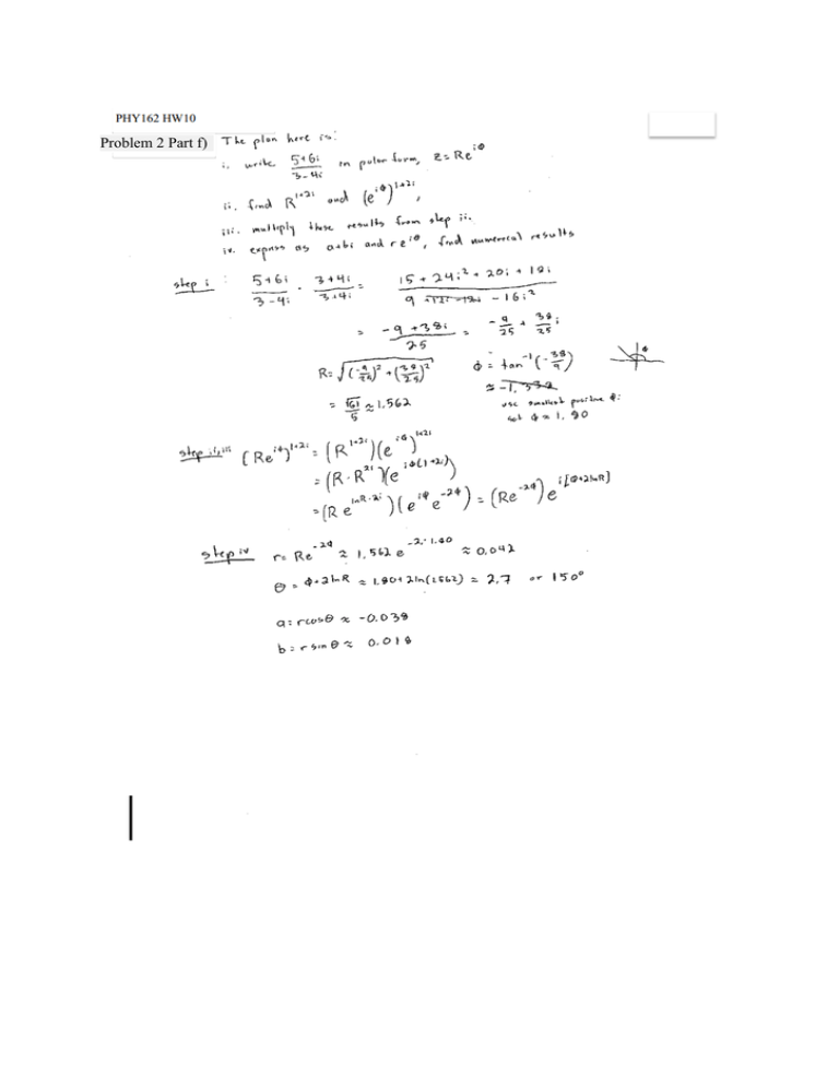
Problem 2 Part f) Problem 3 Problem 3 Cont'd Problem 4 Problem 5 Problem 6 Problem 6 Cont'd Problem 6 Cont'd Answer to 7: The answer to this problem is (D). This is explained on page 10 of Prof. Greenside's file notes-on-AC-circuits.pdf. A simpler quick answer is observe that capacitors act like infinite-resistance device at low frequencies omega and like a zero-resistance wires at high frequencies. So the potential difference V_0 across the capacitor is large at low frequencies and tiny at high frequencies and so the curve must be (D). Answer to 8: The answer is (D), circuits II and III act like high-pass filters. The quick nonmathematical way to see this is that, at low frequencies of a voltage source, a capacitor acts like a high-resistance wire (open circuit). So circuit IV would allow a low-frequency signal through to the output while III would not, and conversely, since a capacitor acts like a low-resistance wire at highfrequencies, III will allow high-frequency signals through but not IV. From the formula Z_L = i omega L for the impedance of an inductor, an inductor at low frequencies as zero impedance and has a large impedance at high frequencies. So circuit I will allow low-frequency but not highfrequency signals to pass through (making I a low-pass filter) while circuit II will let high-frequency signals through but not low-frequency. So II and III are the high-pass filters, while I and IV are low-pass filters. Problem 9
