AN-660 APPLICATION NOTE XY-Matrix Keypad Interface to MicroConverter By Brian Moss
advertisement
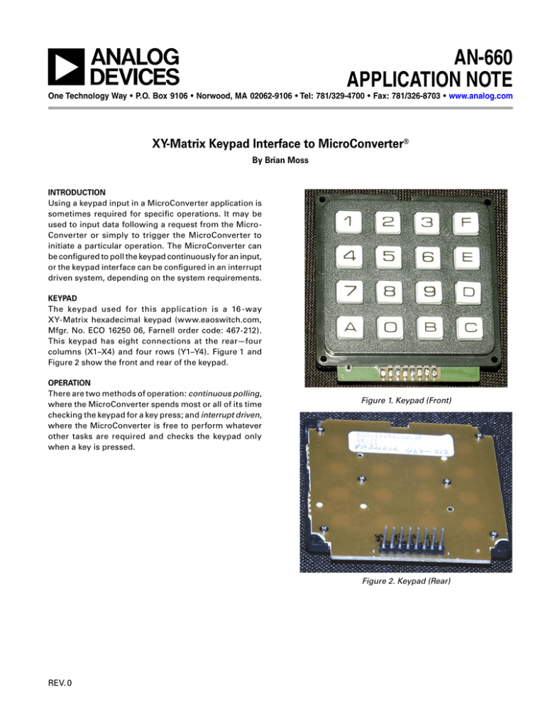
AN-660 APPLICATION NOTE One Technology Way • P.O. Box 9106 • Norwood, MA 02062-9106 • Tel: 781/329-4700 • Fax: 781/326-8703 • www.analog.com XY-Matrix Keypad Interface to MicroConverter® By Brian Moss INTRODUCTION Using a keypad input in a MicroConverter application is sometimes required for specific operations. It may be used to input data following a request from the MicroConverter or simply to trigger the MicroConverter to initiate a particular operation. The MicroConverter can be configured to poll the keypad continuously for an input, or the keypad interface can be configured in an interrupt driven system, depending on the system requirements. KEYPAD The keypad used for this application is a 16 - way XY-Matrix hexadecimal keypad (www.eaoswitch.com, Mfgr. No. ECO 16250 06, Farnell order code: 467-212). This keypad has eight connections at the rear—four columns (X1–X4) and four rows (Y1–Y4). Figure 1 and Figure 2 show the front and rear of the keypad. OPERATION There are two methods of operation: continuous polling, where the MicroConverter spends most or all of its time checking the keypad for a key press; and interrupt driven, where the MicroConverter is free to perform whatever other tasks are required and checks the keypad only when a key is pressed. Figure 1. Keypad (Front) Figure 2. Keypad (Rear) REV. 0 AN-660 VDD 10k� 1 10k� 10k� 10k� 2 3 F VDD ADuC8xx P2.0 Y1 4 5 6 E Y2 P2.1 7 8 9 D A 0 B C Y3 RxD TxD P2.2 RS-232 VDD RST Y4 P2.3 P2.4 X1 P2.5 X2 P2.6 X3 KEYPAD P2.7 X4 Figure 3. Continuous Polling Circuit rows (Y1 to Y2) are connected to the other four port pins (P2.0 to P2.3). The MicroConverter outputs 0 or drives low the keypad rows (P2.0 to P2.3) one at a time and checks the columns (P2.4 to P2.7) for a low condition. Continuous Polling Operations In this mode of operation, the MicroConverter continuously polls the keypad for a key press. This operation is used where the MicroConverter has completed a task and is now waiting for input before proceeding. In this mode, the keypad is connected to one port of the MicroConverter, Port 2 in this example. Figure 3 shows the connectivity. The output from the MicroConverter, following a key press, is viewed using HyperTerminal running on a PC. The MicroConverter is connected to the PC via the COM1 port. This is the reason for showing the RS-232 connection. For example, the following is the sequence of events up to a switch press detection (Switch 5 in this case). The MicroConverter outputs a low on P2.0 (Y1) and checks for a low on P2.4 to P2.7. In this case, no low is found and so it returns P2.0 (Y1) to high and moves on to P2.1 (Y2). The MicroConverter now drives P2.1 (Y2) low and again checks P2.4 to P2.7 for a low condition. This time it finds that P2.5 (X2) is low, due to Switch 5 being pressed. The MicroConverter now knows that the interconnect of Y2 and X2 has been shorted, therefore, this is 5. The code to perform this operation is given in the accompanying KEYSPOLL.ASM file. As can be seen in Figure 3, the four columns (X1 to X4) are pulled up to V DD and are also connected to four of the MicroConverter port pins (P2.4 to P2.7). The four –2– REV. 0 AN-660 VDD 10k� 10k� 10k� VDD 1 2 3 F ADuC8xx 4 5 6 E 10k� Y1 P2.0 Y2 RxD TxD P2.1 7 8 9 D A 0 B C Y3 RS-232 P2.2 VDD RST Y4 P2.3 P2.4 X1 P2.5 X2 P2.6 X3 INT1 P2.7 X4 ������ OUT2 OUT3 OUT1 INT1 GAL 16V8 Figure 4. Interrupt Driven Circuit NOTE: In both circuit diagrams, inherent circuitry critical to the operation of the MicroConverter is omitted for clarity, i.e., EA, PSEN, decoupling, and detailed RST. This circuitry should not be omitted in practice. This negative edge triggers the INT1 interrupt service routine, which in turn runs the keypad software. Once the keypad software routine has run and no additional key presses have been detected, the MicroConverter resumes executing whatever other code it was running before the key was pressed. The code for this application is given in the accompanying KEYSINT.ASM file. Interrupt Driven Operations The basic operation of an interrupt driven scheme is similar to the polling scheme except the MicroConverter does not continuously poll the keypad. Instead, it polls the keypad only when a key is pressed. This operation requires some external circuitry, as shown in Figure 4. The objective of this logic is to produce a negative-going edge for each key press (see the truth table below). X1 X2 OUT1 X3 X4 OUT2 OUT1 OUT2 OUT3 INT1 0 0 1 1 0 1 0 1 1 1 1 0 0 0 1 1 0 1 0 1 1 1 1 0 0 0 1 1 0 1 0 1 0 1 1 0 1 0 0 1 Purchase of licensed I2C components of Analog Devices or one of its sublicensed Associated Companies conveys a license for the purchaser under the Philips I2C Patent Rights to use these components in an I2C system, provided that the system conforms to the I2C Standard Specification as defined by Philips. REV. 0 –3– E03776–0–9/03(0) © 2003 Analog Devices, Inc. All rights reserved. Trademarks and registered trademarks are the property of their respective owners. –4–
