Electronic energy meters and electronic components reliability facturing and failure mechanisms, the
advertisement
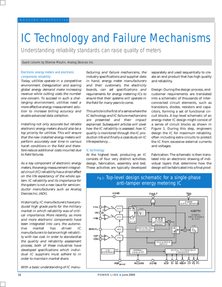
I N D U S T R Y P E R S P E C T I V E IC Technology and Failure Mechanisms Understanding reliability standards can raise quality of meters Guest column by Etienne Moulin, Analog Devices Inc. Electronic energy meters and electronic components reliability Today, utilities operate in a competitive environment. Deregulation and soaring global energy demand make increasing revenue while cutting costs the number one concern. To succeed in such a challenging environment, utilities need a more effective energy measurement solution to increase billing accuracy and enable advanced data collection. Installing not only accurate but reliable electronic energy meters should also be a top priority for utilities. This will ensure that the new installed energy meters will perform accurately over time in various harsh conditions in the field and therefore reduce additional costs incurred due to field failures. As a key component of electronic energy meters, the energy measurement integrated circuit (IC) reliability has a direct effect on the life expectancy of the whole system. IC reliability and its importance for the system is not a new issue for semiconductor manufacturers such as Analog Devices Inc. (ADI). facturing and failure mechanisms, the industry specifications and supplier data in hand, energy meter manufacturers and their customers, the electricity boards, can set specifications and requirements for energy metering ICs to ensure that their systems will operate in the field for many years to come. This article is the first of a series where the IC technology and IC failure mechanisms are presented and their impact explained. Subsequent articles will cover how the IC reliability is assessed, how IC quality is monitored through the IC production life and finally a case study on IC life expectancy… IC technology At the highest level, producing an IC consists of four very distinct activities: design, fabrication, assembly and test. These activities are typically developed Fig 1: Design: During the design process, endcustomer requirements are translated into a schematic of thousands of interconnected circuit elements, such as transistors, diodes, resistors and capacitors, forming a set of functional circuit blocks. A top-level schematic of an energy meter IC design might consist of a series of circuit blocks as shown in Figure 1. During this step, engineers design the IC for maximum reliability, often including extra circuits to protect the IC from excessive external currents and voltages. Fabrication: The schematic is then translated into an electronic drawing of individual layers that determine how the design will be fabricated into a final prod- Top-level design schematic for a single-phase anti-tamper energy metering IC Historically, IC manufacturers have produced high grade parts for the military market in which reliability was of critical importance. More recently, as more and more electronic components have been integrated into cars, the automotive market has driven IC manufacturers to balance high reliability with low cost. In order to standardise the quality and reliability assessment process, both of these industries have developed specifications which individual IC suppliers must adhere to in order to maintain market share. With a basic understanding of IC manu58 separately and used sequentially to create an end product that has high quality and reliability. POWER LINE ● June 2004 I N D U S T R Y Fig 2: Cross-section of a typical CMOS IC with three metal layers P E R S P E C T I V E Fig 4: Automatic test equipment for production of ICs Silicon Dioxide insulator Aluminium interconnect lines Vias between metal lines Contacts to the transistors Transistor gates Gate oxide PMOS transistor Source/Drain and silicon substrate NMOS transistor Source/Drain and PMOS well uct. During the fabrication process, a series of 50 to 100 steps of depositing, doping, patterning and etching different layers of material onto the silicon substrate is used to form the final product. A generic cross-section of a typical silicon IC with complementary positively and negatively doped transistors (PMOS and NMOS respectively, or “CMOS”) and three layers of metal is shown here in Figure 2. Packaging: Once the die is fabricated, it goes through an assembly process, a second series of steps in which the die is bonded or attached to a metal paddle, wirebonds are attached from the die to a set of external leads which can be soldered to a board, and the entire construct is then encapsulated in a plastic mould compound or “package”, as shown in Figure 3. Testing: After the die is packaged, each individual part is tested on automatic test equipment (ATE) (Figure 4). The ATE tests are designed to ensure that every part is functional and meets the datasheet specifications. A welldesigned set of ATE tests will also ensure that outgoing failure rates are very low and will catch parts that are non-functional or will not perform adequately in the energy meter. IC failure mechanisms IC reliability is typically depicted with the bathtub curve shown in Figure 5. This curve shows the failure rate of products with respect to time and is made up of three individual regions related to early life failure, useful life and wear-out. Each region is characterised separately with potential failures classified as quality failures, random failures, and wear-out failures, respectively. The ideal shape of the curve has a brief quality defect/early life failure region and a very long useful life region. By its nature, an IC does not have moving parts and is not susceptible to the Fig 5: of a plastic encapsulated IC component Failure rate Fig 3: Overview Bathtub curve Early life failure W ear-out Useful life Time POWER LINE ● June 2004 wear-out mechanisms typically associated with a mechanical part. However, the IC design, the fabrication process, the assembly process, and the overall product itself all have their own sets of failure mechanisms caused by heat, current, voltage, humidity and temperature extremes. The principal IC failure types and common mechanisms are presented. Early life failures are typically caused by defects and contaminants introduced during processing or handling of the materials used in IC manufacturing. With well-controlled fabrication and assembly processes, very few early life failures will occur. Major IC suppliers, especially those with ISO certification have extremely well-documented processes for every aspect of their businesses, including the fabrication and assembly processes. Electrostatic discharge (ESD) is a single, fast, high current transfer of electrostatic charge between two objects at different electrostatic potentials. If this high current transfer exceeds the maximum rating of the fabrication process, it will damage the IC. Figure 6 shows the damage ESD can cause inside an IC. This type of damage can be caused when the ICs are handled or transported without the use of ESD protection such as ground straps, ESD-resistant trays, tubes or reels, or when assembly machines are not properly grounded. Protection from ESD must be part of the circuit design and the manufacturing environment. ESD, its causes and ways to prevent it, is 59 I N D U S T R Y P E R S P E C T I V E Fig 6: ESD IC failures ination or cratering. These mechanical effects can have a dramatic effect on the thermal efficiency of the IC as well as on its overall reliability, potentially leading to a device failure. Proper selection of materials and welldeveloped assembly processes are both necessary in preventing stress-related failures. Figure 7 shows delamination, cratering and metal shearing stressrelated failures. a very lengthy topic; one place to look for more information is in http:// www.esda.org/aboutesd.html. Latch-up can be caused by the parasitic bipolar transistors inherent to a CMOS design. These parasitic transistors can be activated in various ways and can dominate the CMOS circuit behaviour thus creating electrical overstress failures. The arrangement of individual circuit elements within the design plays a critical role in determining a product’s ability to withstand transient currents (latch-up) or voltages (ESD) without incurring damage. The materials which make up the gate and capacitor oxides, contacts, vias and metal lines in the fabrication process can experience wear-out over time with the application of constant voltage and current. This can lead to opens and shorts in the circuit or simply changes in the electrical characteristics required for the product to function accurately. To delay these failure mechanisms and extend the useful life of the IC, materials and individual process steps within the fabrication process must be specially designed during process development. Fig 7: Delamination 60 Stress-related failures of the package, all of its interfaces and the die itself (cracking, delamination, wire breaks, metal shear), can be caused by the expansions and contractions of the various materials used in the assembly process as the IC experiences temperature extremes over time, such as the change in seasons. Today the majority of integrated circuits are produced in plastic packages. The plastic moulding compound used for the plastic surface-mount component (PSMC) is hydrophilic and absorbs moisture from the surrounding air, reaching a saturation level dependent on the surrounding ambient. The moisture has a relatively benign effect on the reliability of the product unless it has brought some impurities into the body of the package. However, the subsequent printed circuit board manufacturing process subjects the board to extremely high temperatures – up to 260°C in seconds. This rapid rise in temperature vaporises and moisture present in the packages causes it to expand. This expansion of vapour, particularly in the areas of the die attach and lead-frame, can cause a separation of the moulding compound from the die surface or leadframe inducing failure like crack, delam- Stress-related IC failures Catering Metal shearing POWER LINE ● June 2004 With a controlled manufacturing process and contaminant-free fabrication and assembly environments, corrosion will not be an issue. However, if the IC is not properly processed or contaminants are present, the IC can fail due to corrosion. Conclusion An introduction to the process of designing, fabricating, assembling and testing an IC has been presented here. It has been shown that each of these steps is a complex process on its own and requires technical expertise and know-how developed over years of experience. Companies like Analog Devices invest thousands of hours of engineering in understanding these core technologies as they play a critical role in the quality and reliability of their end-product. However, as hard as you can avoid IC failures, they can happen and in order to ensure an extended product lifetime, IC companies also invest heavily in understanding failure mechanisms and their causes. ESD, latch-up, corrosion and stress-related failure mechanisms have been introduced in this article as they represent the major sources of IC failure. In the next article we will present how each of these failures mechanisms can and must be assessed to ensure the lowest IC failure rate. Standard methods developed by international organisations to assess quality of processes and reliability of IC will also be listed. Finally, as quality and reliability are not onetime actions, production quality monitoring as it is done in companies like Analog Devices will be presented. ■
