Document 11623755
advertisement
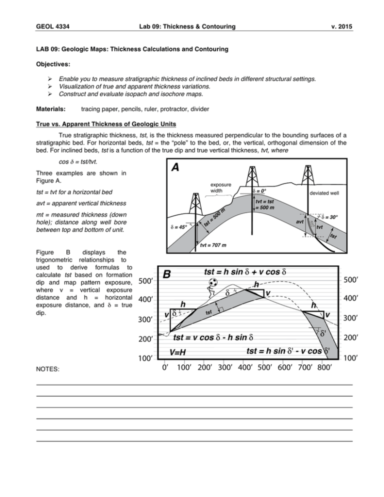
GEOL 4334 Lab 09: Thickness & Contouring v. 2015 LAB 09: Geologic Maps: Thickness Calculations and Contouring Objectives: Ø Ø Ø Enable you to measure stratigraphic thickness of inclined beds in different structural settings. Visualization of true and apparent thickness variations. Construct and evaluate isopach and isochore maps. Materials: tracing paper, pencils, ruler, protractor, divider True vs. Apparent Thickness of Geologic Units True stratigraphic thickness, tst, is the thickness measured perpendicular to the bounding surfaces of a stratigraphic bed. For horizontal beds, tst = the “pole” to the bed, or, the vertical, orthogonal dimension of the bed. For inclined beds, tst is a function of the true dip and true vertical thickness, tvt, where cos δ = tst/tvt. A Three examples are shown in Figure A. exposure width tst = tvt for a horizontal bed δ = 0° tvt = tst = 500 m avt = apparent vertical thickness 0 δ = 45° t= 50 m avt ts δ = 30° mt mt = measured thickness (down hole); distance along well bore between top and bottom of unit. deviated well tvt tst tvt = 707 m Figure B displays the trigonometric relationships to used to derive formulas to calculate tst based on formation dip and map pattern exposure, where v = vertical exposure distance and h = horizontal exposure distance, and δ = true dip. 500’ 300’ v δ 100’ v h v tst = v cos δ - h sin δ 0’ 400’ h tst V=H 500’ h δ 400’ 200’ NOTES: tst = h sin δ + v cos δ B δ' tst = h sin δ' - v cos δ' 100’ 200’ 300’ 400’ 500’ 600’ 700’ 800’ 300’ 200’ 100’ GEOL 4334 Lab 09: Thickness & Contouring v. 2015 Definitions Related to Stratigraphic Thickness Isopach Contour – A line that connects points of equal true stratigraphic thickness (tst) of a unit, as measured perpendicular to bedding. An isopach map represents the variations in tst of a specified unit. Isochore Contour – A line that connects points of equal true vertical thickness (tvt). If a unit is not horizontal, then the vertical thickness represents an “apparent thickness”. Note that this value is distinct from the “apparent vertical thickness” of a deviated well (e.g., Fig. A). An isochore map displays variations in tvt of a specified unit. Types of Contour Maps Net thickness map – map contoured based on net interval thickness. Net pay map – map contoured on the thickness of the net interval containing hydrocarbons. Rock property map – map contoured based on similar rock properties such as porosity, permeability, etc. Visualizing Contour Maps and Structures The following diagram displays an inclined gas reservoir that has been cut by a brittle fault. Can you: 1) identify how the grey unit thickens to the N? 2) visualize and estimate the dip direction of the fault plane? 3) identify the dip direction of the “top” of the grey unit? 4) recognize the strike (s), dip (d) and vertical (v) components of separation along the fault? 5) recognize the piercing points P-P’ and the resulting displacement vector, D? Isochores and Structure Contours (left) oblique perspective of an inclined gas reservoir (grey unit) cut by a high-angle brittle fault. Note that contours of isochores are parallel to the strike lines on the top of the reservoir. D = displacement vector; tvt = true vertical thickness. (right) map view of isochores. Note how a “gap” separates the two surfaces where the fault cuts the reservoir. Such gaps are typical of normal faults in the subsurface. Now is a good time to review a few fundamental structural elements from the “Lines and Planes” lab that pertain to this structure contours. For example, can you identify pitch (or rake), trend, plunge, strike, dip and dip direction on the above diagram? Can you recall the exact definitions and visualize these features in the above figure? If not, then review!

