Macroscopic Tunnel Splittings in Superconducting Phase Qubits
advertisement

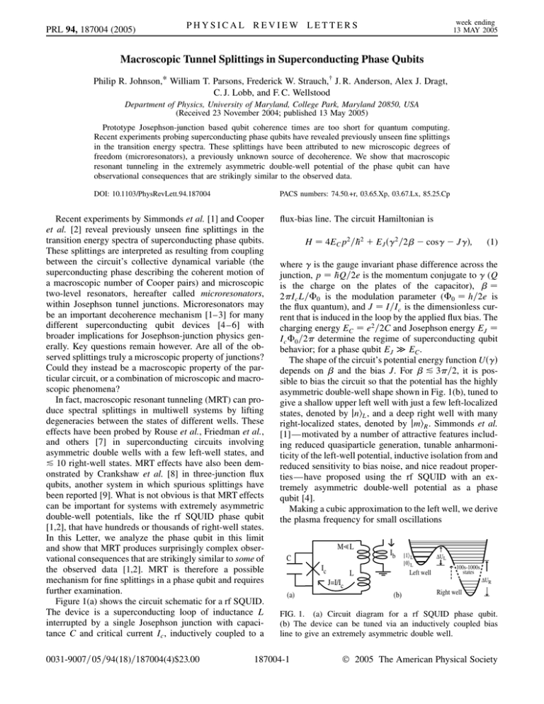
PRL 94, 187004 (2005) week ending 13 MAY 2005 PHYSICAL REVIEW LETTERS Macroscopic Tunnel Splittings in Superconducting Phase Qubits Philip R. Johnson,* William T. Parsons, Frederick W. Strauch,† J. R. Anderson, Alex J. Dragt, C. J. Lobb, and F. C. Wellstood Department of Physics, University of Maryland, College Park, Maryland 20850, USA (Received 23 November 2004; published 13 May 2005) Prototype Josephson-junction based qubit coherence times are too short for quantum computing. Recent experiments probing superconducting phase qubits have revealed previously unseen fine splittings in the transition energy spectra. These splittings have been attributed to new microscopic degrees of freedom (microresonators), a previously unknown source of decoherence. We show that macroscopic resonant tunneling in the extremely asymmetric double-well potential of the phase qubit can have observational consequences that are strikingly similar to the observed data. DOI: 10.1103/PhysRevLett.94.187004 PACS numbers: 74.50.+r, 03.65.Xp, 03.67.Lx, 85.25.Cp Recent experiments by Simmonds et al. [1] and Cooper et al. [2] reveal previously unseen fine splittings in the transition energy spectra of superconducting phase qubits. These splittings are interpreted as resulting from coupling between the circuit’s collective dynamical variable (the superconducting phase describing the coherent motion of a macroscopic number of Cooper pairs) and microscopic two-level resonators, hereafter called microresonators, within Josephson tunnel junctions. Microresonators may be an important decoherence mechanism [1–3] for many different superconducting qubit devices [4 –6] with broader implications for Josephson-junction physics generally. Key questions remain however. Are all of the observed splittings truly a microscopic property of junctions? Could they instead be a macroscopic property of the particular circuit, or a combination of microscopic and macroscopic phenomena? In fact, macroscopic resonant tunneling (MRT) can produce spectral splittings in multiwell systems by lifting degeneracies between the states of different wells. These effects have been probed by Rouse et al., Friedman et al., and others [7] in superconducting circuits involving asymmetric double wells with a few left-well states, and & 10 right-well states. MRT effects have also been demonstrated by Crankshaw et al. [8] in three-junction flux qubits, another system in which spurious splittings have been reported [9]. What is not obvious is that MRT effects can be important for systems with extremely asymmetric double-well potentials, like the rf SQUID phase qubit [1,2], that have hundreds or thousands of right-well states. In this Letter, we analyze the phase qubit in this limit and show that MRT produces surprisingly complex observational consequences that are strikingly similar to some of the observed data [1,2]. MRT is therefore a possible mechanism for fine splittings in a phase qubit and requires further examination. Figure 1(a) shows the circuit schematic for a rf SQUID. The device is a superconducting loop of inductance L interrupted by a single Josephson junction with capacitance C and critical current Ic , inductively coupled to a 0031-9007=05=94(18)=187004(4)$23.00 flux-bias line. The circuit Hamiltonian is H 4EC p2 =h 2 EJ 2 =2 cos J; (1) where is the gauge invariant phase difference across the junction, p hQ=2e is the momentum conjugate to (Q is the charge on the plates of the capacitor), 2Ic L=0 is the modulation parameter (0 h=2e is the flux quantum), and J I=Ic is the dimensionless current that is induced in the loop by the applied flux bias. The charging energy EC e2 =2C and Josephson energy EJ Ic 0 =2 determine the regime of superconducting qubit behavior; for a phase qubit EJ EC . The shape of the circuit’s potential energy function U depends on and the bias J. For & 3=2, it is possible to bias the circuit so that the potential has the highly asymmetric double-well shape shown in Fig. 1(b), tuned to give a shallow upper left well with just a few left-localized states, denoted by jniL , and a deep right well with many right-localized states, denoted by jmiR . Simmonds et al. [1]—motivated by a number of attractive features including reduced quasiparticle generation, tunable anharmoniticity of the left-well potential, inductive isolation from and reduced sensitivity to bias noise, and nice readout properties—have proposed using the rf SQUID with an extremely asymmetric double-well potential as a phase qubit [4]. Making a cubic approximation to the left well, we derive the plasma frequency for small oscillations M L C Ic Ib |1⟩ L |0⟩ L Left well L ∆UL 100s-1000s states ∆UR J=I/Ic (a) (b) Right well FIG. 1. (a) Circuit diagram for a rf SQUID phase qubit. (b) The device can be tuned via an inductively coupled bias line to give an extremely asymmetric double well. 187004-1 2005 The American Physical Society well [region I of Figs. 2(a) and 2(b)] fall with increasing J, and are thus nearly vertical. The energy levels in region III correspond to delocalized states fully above the left well. The dashed line in Fig. 2(a) dividing regions II and III indicates the energy at the top of the left-well barrier. In region II, eigenstates whose energies lie along H branches are primarily localized in the left well (H L). The number of left-well states at bias J is consistent with NL from Eq. (4). Eigenstates whose energies lie along V branches are primarily localized in the right well (V R). Their energies fall at essentially the rate of the falling right well. Note that in Fig. 2(a) the density of right-well states is comparable to that of the left well, despite NR NL . Every apparent intersection of an H and V energy level in Fig. 2(a) is an avoided crossing (see inset). Degeneracies are lifted by resonant tunneling of left-well states jniL and right-well states jmiR : Left of an avoided crossing between k and k 1 eigenstates we find that jki jniL and jk 1i jmiR . Right of the crossing the states swap, becoming jki jmiR and jk p1i ’ jniL . At the avoided crossing p jki jniL jmiR = 2 and jk 1i jniL jmiR = 2: Fig. 2(c) shows the wave functions for the k 641 eigenstate before, at, and after the splitting shown in the inset in Fig. 2(a). The distribution of splitting magnitudes along the first five energy branches are plotted in Fig. 2(d) as solid points. Gaps larger than 1 MHz are within the resolution of recent experiments. Along each left-well energy branch the tunnel splittings are regularly spaced with magnitudes that decrease exponentially with NL . We have numerically computed spectra for a variety of circuit parameters, including Ic 2 A and C 0:5 pF which are comparable to those reported in [2]. In each case the spectrum looks qualitatively similar to Fig. 2(a). We note that the predicted gap sizes are strikingly similar to those reported in [1,2] (1–100 MHz). (2) J 1 2 1=2 1 arccos1 > 1 (3) is the critical bias for which the left well vanishes. Note that the effective critical current is I Ic J > Ic . The approximate number of left-well states is s UL 23=4 EJ NL 1 2 3=8 J J5=4 ; (4) ’ h! L 3 EC where UL is the barrier height. The level spacing in the right well is approximately h! R , where !R is the rightwell plasma frequency, and the number of right-well states is approximately NR ’ UR =h! R , where UR is the depth of the right well. Figure 2(a) shows the energy spectrum as J is varied for 0 NL 6 and C 1:2 pF, L 168 pH, and Ic 8:531 A, giving 4:355, I 11:659 A, and !L =2 10 GHz. These are the circuit parameters from [1], assuming that the critical current quoted there is I . To obtain the energy spectrum we diagonalize the Hamiltonian in Eq. (1) using a discrete Fourier grid representation [10], thereby obtaining a numerical solution for the eigenvalues Ek J and eigenstates jkJi of the full double-well system versus the bias J. A harmonic approximation to the right well yields approximately 500 states below the left well; the full calculation yields NR ’ 600–700 states, depending on the bias [11]. In Fig. 2(a) we define the zero of energy to be at the bottom of the left well. We note two different types of energy levels: horizontal (H) branches and near vertical (V) branches. From our definition of zero energy, eigenvalues corresponding to states mainly localized in the right L MHz 80 642 3 2 1 III (b) 40 4 30 641 L 0 NL 3.0230 3.0238 100 L 3 L 2 20 10 L 1 L II 0 GHz 40 ∆ = 15 MHz L MHz !L !0 1 2 1=8 2J J1=4 ; p where !0 8Ec EJ =h 2 , and 4 week ending 13 MAY 2005 PHYSICAL REVIEW LETTERS PRL 94, 187004 (2005) L 0 10 1 L L 5 4 3 I (a) 0 2 1 NL 0 (c) 6 5 (d) 4 3 2 FIG. 2. (a) Numerically computed spectrum of phase qubit when Ic 8:531 A, C 1:2 pF, and L 168 pH ( 4:355). Energies are plotted in units of frequency. The inset shows the avoided crossing due to resonant tunnel coupling between the left-well state j1iL and a highly excited right-well state. (b) The circuit parameters give an asymmetric double well like that shown. (c) Wave functions of the k 641 eigenstate for bias values near the avoided crossing shown in the inset. (d) Solid points show the numerically computed sizes and locations of the splittings. Solid lines are splitting sizes derived from WKB theory. 187004-2 PHYSICAL REVIEW LETTERS PRL 94, 187004 (2005) The complex collection of energy splittings has both direct and indirect effects that should be taken into account when analyzing the experimental data. Consider a double frequency microwave spectroscopic method, like that used in [1]. Microwaves of frequency !01 are applied to drive the 0 ! 1 transition. Excitation of the j1iL state is detected with a measurement microwave pulse of frequency !13 , which drives the 1 ! 3 transition. The j3iL state’s exponentially greater amplitude to be found in the right well compared to the j0iL and j1iL states allows an adjacent detection SQUID to easily detect the change in the qubit’s flux. This method directly probes splittings along many of the energy branches shown in Fig. 2(d). Cooper et al. have introduced a new spectroscopic technique that can probe deeper left wells where NL > 4. This method applies a few-nanosecond current pulse changing the bias so that NL * 2 by briefly tilting the potential adiabatically with respect to the left-well period TL 2=!L 100 ps [2]. Since the measurement pulse moves left-well states to the right along horizontal (H) energy branches [see Fig. 2(a)], readout should be influenced by the exponentially larger splittings present for smaller NL . For example, the measurement pulse may move a deep well state to one of the large splitting degeneracies near NL 2, whose presence may produce a significant perturbation on readout fidelity. Thus the current pulse method is also sensitive to large splittings along multiple energy branches. MRT degeneracies also have very narrow bias-value widths. For example, the inset of Fig. 2(a) shows a splitting width of less than 0.1 nA. The bias widths become only smaller for splittings at larger NL . The horizontal axis of Fig. 2(a) corresponds to more than 300 nA. Typical experiments sampling only a limited number of bias values likely probe only a subset of the (many) MRT splittings. Changes in experimental conditions (e.g., bias drift and noise, or temperature cycling) may generate surprisingly large shifts 9.250 Splitting in 0 L GHz ∆ = 17 MHz 9.230 (a) 9.210 2.018 10.32 Splitting in 1 L GHz 2.016 N 2.014 L ∆ = 24 MHz 10.30 10.28 105 1 L (b) 2.898 2.897 2.896 2.895 NL Splittings and level spacings (GHz) Transition frequencies: 0 L 104 103 102 NR ∆ = (dashed) 102 L ∆R = (thin) 10 ∆splittings = (bold) nL = 2 1 10-1 nL = 1 10-2 nL = 0 10-3 in the observed splitting distributions if they result in a different subset of sampled MRT degeneracies. These or other features could result in transition spectra with a varying distribution of splitting sizes and bias-value locations which, due to their complexity and variability in time, might appear to have a microscopic origin. Such variations seem more consistent with a model of microscopic critical current fluctuators, suggesting that both MRT and microresonator effects are present [12]. If this is the case, it is important to identify which observed splittings are due to which mechanism. Measured with sufficient resolution, transition frequency avoided crossings due to MRT should have distinctive characteristics. When driving 0 ! 1 transitions, a splitting in the j0iL branch should produce crossings like that shown in Fig. 3(a), whereas a splitting in the j1iL branch should produce crossings like that shown in Fig. 3(b). The observed shapes may be strongly dependent upon the experimental measurement technique. Bias noise could smear out the splittings in the horizontal direction. For splittings in the lower energy branch [Fig. 3(a)] this would leave a distinct frequency gap, giving observed splittings horizontally smeared appearances like those observed in [1,2]. In contrast, it is unclear if splittings in the upper branch [Fig. 3(b)] are consistent with observation. Improved experimental resolution that revealed these distinctive avoided crossing shapes would be compelling evidence for MRT. Han et al. have explored other complexities that arise when measuring systems that exhibit MRT [7]. We derive an analytic expression for the energy splitting between pairwise degenerate left and right states in an asymmetric double well in the WKB approximation [13]. This yields the splitting formula v u 1 nL 1=2 u 2 mR 12mR 1=2 S L R nL 2 t e ; nL !mR !enL mR 1 EC/EJ 10-8 10-6 v u u 21=2 L R 432NL nL =21=4 e18NL =5 : ’t nL !3=2 10-4 FIG. 3. (a) The distinctive shapes of avoided crossings in the measured transition frequencies for splittings in the lower branch. (b) The avoided crossing transition shape for splittings in the upper branch. (c) The figure shows that R L over an extremely large range of double-well circuit parameters. Bold lines show the splitting magnitudes along the nL 0, 1, and 2 left-well energy branches, with 4:5, NL 3, and Ic 10 A. (5) R p where S 21 2mE Vd, m C0 =22 , and 1;2 are the classical turning points for the barrier given by L , R ’ h! R are the left- and V1;2 EnL , and L ’ h! right-well level spacings at energy EnL . For deep right wells, Eq. (5) becomes independent of mR . In this limit, together with the cubic approximation accurate for shallow left wells, the splittings are approximately (c) 10-4 week ending 13 MAY 2005 (6) For the right-well level spacing we use the WKB estimate R 2h=T cl [14], where Tcl is the classical period of right-well oscillations with energy EnL : Splittings calculated from Eq. (6) are shown as solid lines in Fig. 2(d). The agreement with the exact splittings (solid points) is excellent for lower lying states, and surprisingly good for the 187004-3 PRL 94, 187004 (2005) PHYSICAL REVIEW LETTERS excited states. Note that the tunnel splitting formula in Eq. (6) predicts splittings exponentially larger than continuum tunneling rates: splitting = tunneling exp18NL =5; making MRT effects important even when continuum tunneling is negligible. We have compared MRT splittings with Eq. (6) for a number of numerical examples with NR 100–1000, but in principle one can fabricate circuits with many thousands of right-well states. The WKB formula for the splittings and level spacings allows analysis of circuit parameters for very deep right wells where numerical treatment is impractical. Figure 3(c) shows h! L ’ L (dashed line) and R 2h=T cl (thin, solid line) versus the ratio EC =EJ for Ic 10 A, NL 3, and 4:5 just below the threshold where the potential develops three wells. (For the circuit parameters in Fig. 2 and [2], EC =EJ 104 –106 .) The value of Ic determines the frequency scale on the left of Fig. 3(c) but leaves the relative positions of the plotted lines essentially unchanged. The top axis shows NR from the harmonic oscillator approximation. Observe that, perhaps unexpectedly, R L even for extremely asymmetric double wells. The bold, solid lines show the WKB splitting when nL 0, 1, and 2. The validity condition for MRT R;L is satisfied over a large range of circuit parameters, and for NR 105 and greater. Dissipation suppresses resonant tunneling when R * R , where R ’ NR h=T 1 is the width of excited right-well states, and T1 is the dissipation time for j1iR ! j0iR [15,16]. Using the WKB expression for R , we find the condition NR & !L T1 for observing MRT. For a phase qubit with !L =2 10 GHz and T1 10–100 ns, resonant tunneling should be detectable as long as NR & 600–6000 states. For the circuit parameters in Fig. 2 NR 600–700 and for those in [2] NR 150–300, with a measured T1 ’ 25 ns. Thus, we do not believe that dissipation will remove the effects of MRT. If the intrinsic dissipation is actually much smaller so that & [16], it should be possible to observe coherent oscillations [17]. In conclusion, we show that significant MRT effects should be present for extremely asymmetric double-well phase qubits, and thus MRT should be taken into account in the important effort to fully characterize microresonators or other splittings mechanisms. Our analysis provides tools and can guide experiments to help distinguish between three main possibilities: (1) Both MRT and microresonators are present, (2) MRT effects explain all the observational data, and (3) MRT is entirely absent. We believe that (1) is most likely; however, due to the complexity of effects from MRT, further experiments and detailed modeling are necessary to definitively rule out (2) and (3). Finally, our Letter provides general tools for exploring the quantum mechanics of extremely asymmetric double-well systems. We thank R. Simmonds and J. Martinis for useful comments. This work was supported by the NSA, the DCI Postdoctoral Research Program, the NSF QUBIC week ending 13 MAY 2005 Program, DOE Grant No. DE-FG02-96ER40949, and the University of Maryland’s Center for Superconductivity Research. *Electronic address: philipj@physics.umd.edu † Electronic address: fstrauch@physics.umd.edu [1] R. W. Simmonds et al., Phys. Rev. Lett. 93, 077003 (2004). [2] K. B. Cooper et al., Phys. Rev. Lett. 93, 180401 (2004). [3] D. J. Van Harlingen et al., Phys. Rev. B 70, 064517 (2004); F. Meier and D. Loss, Phys. Rev. B 71, 094519 (2005). [4] J. M. Martinis, S. Nam, J. Aumentado, and C. Urbina, Phys. Rev. Lett. 89, 117901 (2002); Y. Yu et al., Science 296, 889 (2002); A. J. Berkley et al., ibid. 300, 1548 (2003); F. W. Strauch et al., Phys. Rev. Lett. 91, 167005 (2003); H. Xu et al., ibid. 94, 027003 (2005). [5] T. Yamamoto et al., Nature (London) 425, 941 (2003); Yu. A. Pashkin et al., ibid. 421, 823 (2003); A. Wallraff et al., ibid. 431, 162 (2004); D. Vion et al., Science 296, 886 (2002). [6] C. H. van der Wal et al., Science 290, 773 (2000); I. Chiorescu, Y. Nakamura, C. J. P. M. Harmans, and J. E. Mooij, Science 299, 1869 (2003); A. Izmalkov et al., Phys. Rev. Lett. 93, 037003 (2004); Y. Yu et al., ibid. 92, 117904 (2004); L. Tian, S. Lloyd, and T. P. Orlando, Phys. Rev. B 67, 220505 (2003). [7] R. Rouse, S. Han, and J. E. Lukens, Phys. Rev. Lett. 75, 1614 (1995); S. Han, R. Rouse, and J. E. Lukens, ibid. 84, 1300 (2000); J. R. Friedman et al., Nature (London) 406, 43 (2000); D. V. Averin, J. R. Friedman, and J. E. Lukens, Phys. Rev. B 62, 11 802 (2000). [8] D. S. Crankshaw et al., Phys. Rev. B 69, 144518 (2004). [9] P. Bertet et al., cond-mat/0412485; B. L. T. Plourde et al., cond-mat/0501679. [10] C. C. Marston and G. G. Balint-Kurti, J. Chem. Phys. 91, 3571 (1989). [11] Figure 1b of [1] shows NR 2500. [12] R. Simmonds and J. Martinis (private communication). [13] We derived Eq. (5) from Herring’s formula assuming a WKB wave function under the barrier and matching onto excited harmonic oscillator states in the two wells. This method is described in A. Garg, Am. J. Phys. 68, 430 (2000). See also J. M. Schmidt, A. N. Cleland, and J. Clarke, Phys. Rev. B 43, 229 (1991). [14] L. D. Landau and E. M. Lifshitz, Quantum Mechanics, Vol. III, (Pergamon, London, 1965). [15] A. O. Caldeira and A. J. Leggett, Ann. Phys. (N.Y.) 149, 374 (1983). [16] A. Garg, Phys. Rev. B 51, 15 161 (1995). [17] It is interesting to speculate that unexpectedly short dissipation times of 25 ns in [2] result from damping of excited right-well states, such that Tmeasured T1 =NR . This would imply a T1 of a few s, consistent with the expected relaxation times (see footnote [11] in [2]). The existence of tunnel splittings could also be probed by tuning T1 through adjustable coupling to adjacent circuit elements. 187004-4


