An implementation of the Schwartz-Neumann Alternating Method for
advertisement
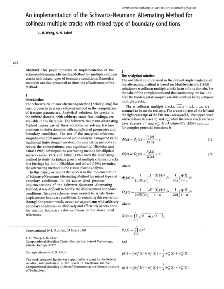
Computational Mechanics 16 (1995) 266 271 9 Springer-Verlag 1995
An implementation of the Schwartz-Neumann Alternating Method for
collinear multiple crackswith mixed type of boundary conditions
L. H. Wang, S. N. Atluri
266
Abstract This paper presents an implementation of the
Schwartz-Neumann Alternating Method for multiple collinear
cracks with mixed types of boundary conditions. Numerical
examples are also presented to show the effectiveness of the
method.
2
The analytical solution
The analytical solution used in the present implementation of
the alternating method is based on Muskhelishvili's (1953)
solution to n collinear multiple cracks in an infinite domain. For
the sake of the completeness and the consistency, we include
1
here the fundamental complex variable solution to the collinear
Introduction
multiple cracks.
The Schwartz-Neumann Alternating Method [Atluri (1986) ] has
The n collinear multiple cracks, a~bi,i = 1,2 . . . . . n, are
been proven to be a very efficient method in the computation
assumed
to be on the real axis. The x-coordinates of the left and
of fracture parameters. Analytical solutions for cracks in
the
right
crack
tips of the i'th crack are ai and b~.The upper crack
the infinite domain, with arbitrary crack-face loadings, are
surfaces have stresses ~§ and rr+,ywhile the lower crack surfaces
available in the literature. The Schwartz-Neumann Alternating
have stresses ~ and a~r. Muskhelishvili's (1953) solution
Method makes use of these solutions in solving fracture
for complex potential functions is
problems in finite domains with complicated geometries and
boundary conditions. The use of the analytical solutions
P~(z)
simplifies the FEM models used in the analysis. Compared to the r
(1)
= Co(z) + Z ( ~ -- ~
traditional finite element method, the alternating method can
reduce the computational cost significantly. Nishioka and
Atluri (1983) developed the alternating method for elliptical
Pn(z) ' ~
(2)
n ( z ) = no(z) + X ~ Y -~
surface cracks. Park and Atluri (1992) used the alternating
method to study the fatigue growth of multiple collinear cracks
in a fuselage lap-joint. Nikishkov and Atluri (1994) extended
where
the alternating method to the elastic-plastic analysis.
In this paper, we report the success in the implementation
1 ~X+(t)p(t)
1 q(t) dt
of Schwartz-Neumann Alternating Method for mixed types of
q)~
t----z d t + ~ i ! t - z
boundary conditions. In the above cited previous
implementations of the Schwartz-Neumann Alternating
Method, it was difficult to handle the displacement boundary
1 ~X+(t)p(t) dt_l_~ q(t) dt
conditions. Iterative schemes were needed to satisfy these
[2~
tZz
2niLt-z
displacement boundary conditions. In removing this restriction
through the present work, we can solve problems with arbitrary
where
boundary conditions as effectively and efficiently as was done
for traction boundary value problems in the above cited
references.
k=l
Communicated by S. N. Atluri, 29 March 1995
P,(z)=fiGz k
k=0
L. H. Wang, S. N. Atluri
Computational Modeling Center, Georgia Institute of Technology,
Atlanta, Georgia 30332
and
Correspondenceto: S. N. Atluri
p(t) = 89
i
(t) + try (t)] - ~ [(r~(t) + a~(t)]
The work presented herein was supported by a grant for the Federal
Aviation Administration to the Center of Excellence for the
Computational Modeling of Aircraft Structures at the GeorgiaInstitute q(t) = ~[~; (t) - o ; (t)] - ~i [ G ( t ) - G ( t ) ]
of Technology.
The integration path L is the union of all the cracks a;b;,
i = 1, 2 . . . . . n. The + sign in X + (t) indicates that the upper
surface value of the function X(t) is taken in the integration.
c, and a are determined by the stress and the rigid body
rotation at the infinity, q, k = 0, 1. . . . . n - 1 are determined by
the uniqueness conditions of the displacements.
in the evaluation of stress, Park (1993) used a set of approximate
piecewise constant functions. Following the same philosophy,
we use a set of approximate piecewise linear base functions.
Actually, they are exactly piecewise linear base functions for
a single crack.
We can use the following functions to approximate the linear
base functions with non-zero values on [d - e, d + e] on the
K ~ q?(z) dz - ~ -Q(e) de = 0
crack aib i.
Vl
i = 1, 2 . . . . . n.
(3)
&
p(t) =
where
{
3
-
-
tx/-~--a x / t - b
X+(d~)(t-de)
te[d-e,d+e]c[ai,
4v plane strain
K=
1~
b ~]
other
plane stress
(11)
and Fr is the contour surrounding the i'th crack
a~b~,i = 1,2 . . . . . n.
The stresses and displacements are given by
a~+ o-y= 2[~(z) + aS(z)]
%-i%=
(4)
qS(z) + ~ ( ~ ) + ( z - i )
r
2#(u + iv) = K(9(Z) -- co(Y.) -- (z --s @(z)
(5)
(6)
where r
= ~P(z) and cd(z) = q~(z).
and G must be zero if there are no stresses and no rigid
body rotation at infinity. In the alternating method, q(t) =- O,
because a y+ -= orand a xy+ -= rr-.
Thus, the complex potentials
y
xy
[Eq. (1) and Eq. (2)] can be simplified as
P(z)+iP.(z)
~0(z) =$2(z) 2~iX(z)
where a = a i, b = bi, de = d + e and do = d T- e. It can be easily
verified that p (de) = 0 and p(d~) = 1. p (t) is the linear function
of t in [d - e, d + el when the number of the cracks is one. The
error of the approximation decreases as e ~ 0 for multiple
cracks. Using this approximation, the Cauchy integral in Eq. (8)
can be evaluated as in the following:
r(z) =
[F(d + e, z) - F ( d - e, z)]
b
(12)
where
k(t,z): [.x/[Z~-ax/-iCbt-dedt
t--Z
(7)
:tx/~--ax/-t~[
(t-a)+(t-b)4
+ (z - de)]
where
F(z)
X+(d~)
=
-] x + p ( t ) dt
(8)
L t--z
The uniqueness conditions of the displacements [Eq. (3)] can
be simplified as
e--'''~uJiz)az=O i = 1 , 2 . . . . . n.
(9)
9in
.
.
.
.
.
+ [(Z -- de)(2z - a - b) - ~ ( a - b) 2]
<
if the contours ~ , i = 1, 2,..., n are symmetric about the real
axis. This set of equations leads to the following linear system
9ln (xft - a + x / t - b)
The derivative of F(z) is
(lO)
Kqcj=r i i , j = 1,2 . . . . . n
[F'(Z)=~~[
l+z-d~z_td
where
KO
-
~ z)-~
~x~dz
and
i ~ F(Z) d z
ri= <X(z)
-- (a + b + 2dr
In ( V t -- a + x / ~ - - b)
2.1
The Cauchy integral
The crack surface loads can be represented by a set of linearly
independent base functions. Park and Atluri (1992) used a set
of Delta functions as base functions. To improve the accuracy
,,/;G-a , / b - z - , / ; G , / a
- z
267
The derivative of 12(z) is
s
= [ " ( z ) + t ,(z)
1
2
2zciX(z)
k=l
+
Z -- a k
2.2
The strains, stresses, displacements and stress intensity factors
The stresses, displacement gradients and displacements are
given by
268
G + % = 2 [s
(13)
+/-2(z)]
%-i%=O(z)+S2(e)+(z-e)O'(z)
(14)
2/~(u + iv) = xo)(z) --o)(Y.) -- (z --~)l-2(z)
(15)
2#(ux + iVx) = Kf2(z) - I2(~) -- (z - - s
(16)
2~(vy--iuy) =K/'2(z) +.(2(2) +
(z--i)g2'(z)
in the infinite domain subjected to certain crack surface loading
as described in the previous section. The other one has the same
finite geometry as the original problem except that the cracks
are ignored. The second problem is solved by using the
finite element method. Since the cracks are ignored, the
boundary of the FEM model is F = / ' ~ w F~.
We discretize the uncracked finite domain using a FEM
model. Let the prescribed displacements (including the zero
displacements) on /'u be u = {lTi}, i = 1, 2. . . . . n~. Let the
prescribed tractions (including zero tractions) on F~ be t = {~,
i = 1, 2 . . . . . n,. Let the sampling points of tractions on the
locations of the crack surfaces F~ be Pi, i = 1, 2 . . . . . np. The
tractions at these sampling points are denoted as T = {Ti},
i = 1,2 . . . . . n r.
We can solve for the crack surface tractions T for any given
boundary loads u and t using the finite element method. Due
to the linearity of the problem, we can denote the solution
procedure as
T = KUu + K t t
--2/2(z)
(17)
(19)
where K u and K t are linear operators of dimension {nr, nu} and
where o'(z) = g2(z).
The stress intensity factor is
K~ -- iK~z = lim
x~a k
We can take the tractions T as the crack surface loads applied
on the n collinear cracks in the infinite domain. Using the
analytical solution, we can find the displacements u at the
2x/~k -- x) (a z -- ia v ) for the left crack tip ak location of Pu and the tractions t at the location of F t. Similarly,
we denote these solutions as
Kf - iK~ = lira ~ ( a y
x
- i a . ) for the right crack tip
bk
bk
u=KUT
m
t = KtT
They are
2
- )~X.b)
(bk----ak) [F(Gb) + iP"(x"b)t
(18)
(20)
(21)
where K" and K t are linear operators of dimension (n,, nr) and
(nt, nr).
The boundary conditions for the original problem are u = u s
and t = t ~ Since the crack surfaces are traction free, T = 0. We
try to find the additional loads u a and t a such that
where
T = KU(u~ + u ~) + K t ( t ~ + t ~)
for the left crack tip a k
Zab =
Nab =
i
bk
for the right crack tip b k
u" = K u T
for the left crack tip a k
t a = K tT
for the right crack tip b k
Subtracting the analytical solution from the FEM solution, we
get the solution to the original problem.
The existence of such loads u s and t a is shown in the following.
Eliminating T in the above equations, we have
and
(I - A ) X = r
l=l,lq:k
where
3
Schwartz-Neumann Alternating Method
Consider the case in which the n collinear cracks are in a finite
domain. The crack surfaces are denoted collectively as/',. Let
the boundary of the finite domain (not including the crack
surface) be F. The boundary with prescribed tractions is F~.
The boundary with prescribed displacements is Ft. We have
e=Gur,.
We make use of two simpler problems in order to solve the
original problem. One of them is that of the n collinear cracks
I K ~ K ~ ~-~Kt~
A =
-~K ~ WK t]
X=
t~
(22)
and I is the identity operator. The linear system Eq. (22) has
an unique solution if I - A is not singular. If I - A is singular,
there must exist a non-zero X such that ( I - A ) X = 0, which
means that there exists a non-zero T such that
T = K " ( u " ) + K t ( t a)
u ~ = KUT
m
t ~= KtT
In this case, if we subtract the analytical solution from the FEM
solution, we obtain the solution to the following problem. The
geometry is the same as the original problem, while the whole
boundary F is free of external loadings. The crack surfaces are
traction free. The FEM solution gives zero displacements for
the crack surfaces, while the analytical solution gives non-zero
displacements for the crack surfaces because of the non-zero
T. Thus, the resulting solution has non-zero displacements at
the crack surfaces. Since the cracks can not be opened without
any external load, we have a contradiction. Therefore, I - A
can not be singular.
It is very expensive to find X by inverting I - A. An alternate
iterative scheme can be devised as:
Xi+l=AXi
i=0,1,2 ..... ~
u = 0 and t = 0 on F than twice as much as it does in the infinite
domain, the alternating method [Eq. (23)] described above
converges.
We can expect quick convergences for most of the practical
applications. For any crack surface displacements, the
displacement and stress at a point decay rapidly as the point
moves away from the crack surfaces. Thus, the work done in
the finite domain with the homogeneous boundary condition
is very close to the work done in the infinite domain, which
implies that the eigenvalues of A are very small.
269
4
Examples
4.1
Periodic collinear cracks
First, we consider the problem of periodic collinear cracks in
an infinite domain, subjected to the far field loadings. Only
upper half of the body is modelled in the FEM analysis because
of the symmetry. Mixed boundary conditions are specified on
the left and right side of the block to ensure the periodic
condition. The dimensions used in the FEM analysis are shown
in Fig. 1. The single FEM mesh in the analysis is shown in Fig. 2.
The results are compared to the analytical solutions [Anderson
(23)
G=I
where X ~ {u ~ to} ~. This fixed point iteration scheme
converges if all the eigenvalues of A are in the open interval
( - 1, 1). If this procedure converges, the solution is
X=
~X
_TTTTTITTTTTTT
2W=2
i
i=1
The eigenvalues of A are smaller than 1. Let X~ be an
eigenvector of A corresponding to the eigenvalue ),
2a
"r
"
H=IO
T = K " ( u ~) + K t ( # )
,~u 2
=
~T
)~t;~= K--~T
Subtracting 2 times the FEM solution from the analytical
solution, we have the following solutions, u = 0 and t = 0 on
_F and the crack surface loading is ( 1 - 2 ) T , while the
displacements at the crack surface are the same as those in the
analytical solution. If the work done in opening the cracks in
the infinite domain is W, the work done in opening the
cracks in the finite domain (with the boundary condition u = 0
and t = 0) is (1 - .~) W, which is equal to the strain energy stored
in the body. It must be positive. Thus, 2 < 1. It can be shown
that 3~=>_0 if there is no boundary with prescribed displacements,
i.e. there is no F~. In this case, the alternating method
converges for cracks in finite domains with arbitrary shapes.
In general, 2 can be negative. We have )~ > - 1 if
(1 - )~) W < 2W, Thus, We h a v e the following form of
convergence criterion. For an arbitrary distribution of crack
surface displacements, if the crack surface loads do less work
in the finite domain with the homogeneous boundary condition
Fig. 1. Periodic collinear cracks in an infinite domain, subjected to
the uniform far field loading
lip
Fig. 2. The FEM mesh used for the periodic cracks at different a/W
5.5
- -
5.0
.......
4.5
/
Periodic cracks
Single crack
//
4.0
3.5
Fig. 5. The FEM mesh for the hole cracks, modelling the upper half
of the body
3.0
2.5
2.0
1.5
270
1.0
0.5
0
0
i
I
I
I
I
I
I
I
I
0.1
0.2
0.3
0.4
0.5
0.6
0.7
0.8
0.9
.0
Fig. 3. Normalised stress intensity factors K~versus the normalised
crack lengths a/W
Fig. 6. The FEM mesh for the hole cracks, modelling one quarter of
the body
(1991)1.
1.30
d
1.25 !
K1 = r~x / - ~ I~--a tari \2W,]
( 7~a ~]"2
]
(24)
1.20
where 2a is the crack length. Figure 3 shows the normalised
stress intensity factor ~ = Ki/ax/-W. The solution of the
alternating method agrees well with the analytical solution. The
error increases as the a/W becomes very large. It is noticed that
there are only one and half elements from the crack tip to the
closest boundary for a/W = 0.85. The alternating method
gives good result even for this case.
1.15
/
1.10
1.05
6
1.00
Using the mesh in Fig. 5
0.95
4.2
Cracks emanating from holes
0.90
Now, we consider the problem with cracks emanating from two
holes. The details are shown in Fig. 4. The problem is
bi-symmetric. First, we solve the problem by modelling only
the upper half, in which we only deal with traction boundary
conditions. The mesh is shown in Fig. 5. Then, we use the
symmetric condition and model only the upper left quarter, in
which we have to deal with mixed boundary conditions. The
mesh used is shown in Fig. 6. Figure 7 shows the convergence
T I
I
T T
2.00
0
r,l.OO
1
.
.
.
2
;
3
4
,
,
6
7
9
Fig. 7. Stress intensity factors K/versus the number of iterations
of the stress intensity factors at the inner crack tip A for the
two different approaches. The convergent rates are almost the
same. Thus, the alternating method for the mixed boundary
conditions enables us to substantially reduce the computational
cost by using displacement boundary conditions.
5
Summary
G= 1.00
T I
.
0
;.
Fig. 4. Cracks emanating from two holes
1.00
,
r,
The implementation of the Schwartz-Neumann Alternating
Method for collinear multiple cracks with mixed types of
boundary conditions has been presented. The convergence rate
is related to the ratio of the energies needed to have the same
arbitrary crack surface displacements in the following two
problems. The first is that of the cracks in an infinite domain.
The second is the same as the original one except that all the
prescribed tractions and displacements are set to zeroes. The
closer the ratio is to the unity, the faster the procedure
converges. If the ratio for any surface displacement is smaller
than 1/2, this procedure will fail to converge. Fortunately, this
will not occur in most of the applications in the practice. The
efficiency and effectiveness are shown by the numerical
examples.
References
Muskhelishvili, N. I. 1953: Some Basic Problems of the Mathematical
Theory of Elasticity, Noordhoo, Groningen
Nishioka, T.; Atluri, S. N. 1983: Analytical solution for embedded
elliptical cracks, and finite element alternating method for elliptical
surface cracks, subjected to arbitrary loadings. Engineering Fracture
Mechanics. 17(3) 247-~268
Atluri, S. N. 1986: Computational methods in the mechanics of fracture.
Amsterdam: North Holland, also translated in Russian, Mir Publishers,
Moscow
Murakami, Y. et al. 1987: Stress intensity factors handbook. Pergamon
press, Oxford
Anderson, T. L. 1991: Fracture Mechanics: fundamentals and
applications. CRC Press
Park, J. H.; Afluri, S. N. 1992: Fatigue Growth of Multiple-Cracks
Near a Row of Fastener-Holes in a Fuselage Lap-loint, Durability
of Metal Aircraft Structures, proceedings of the international
workshop on structural integrity of aging airplanes, Atlanta.
pp. 91-116. Also, Computational Mechanics. Vol. 13 No. 3 Dec, 1993.
pp. 189-203
Park, J. H. 1993: Improvement of the Accuracy of Stress Fields in
Multiple Hole Crack Problems. Internal Report for Computational
Modeling Center, Georgia Institute of Technology
Nikishkov, G. P.; Afluri, S. N. 1994: An analytical-numericalalternating
method for elastic-plasticanalysis of cracks. Computational Mechanics.
Vol. 13 No. 6 Mar pp. 427-442
271

