Active Exterior Cloaking
advertisement
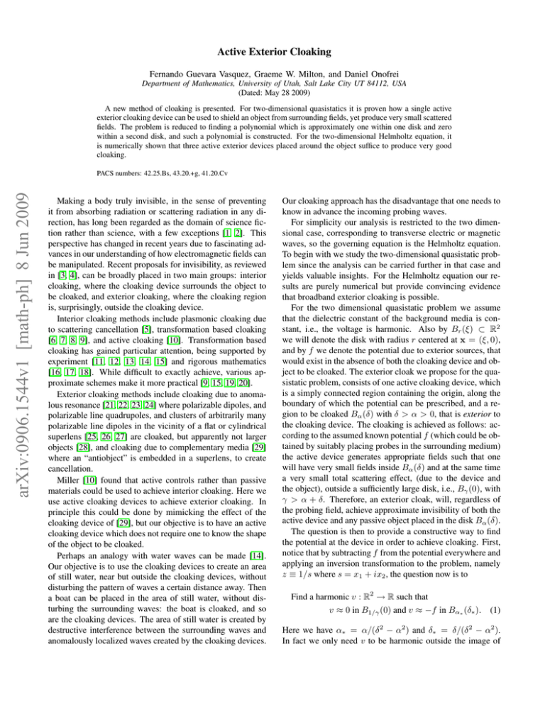
Active Exterior Cloaking Fernando Guevara Vasquez, Graeme W. Milton, and Daniel Onofrei Department of Mathematics, University of Utah, Salt Lake City UT 84112, USA (Dated: May 28 2009) A new method of cloaking is presented. For two-dimensional quasistatics it is proven how a single active exterior cloaking device can be used to shield an object from surrounding fields, yet produce very small scattered fields. The problem is reduced to finding a polynomial which is approximately one within one disk and zero within a second disk, and such a polynomial is constructed. For the two-dimensional Helmholtz equation, it is numerically shown that three active exterior devices placed around the object suffice to produce very good cloaking. arXiv:0906.1544v1 [math-ph] 8 Jun 2009 PACS numbers: 42.25.Bs, 43.20.+g, 41.20.Cv Making a body truly invisible, in the sense of preventing it from absorbing radiation or scattering radiation in any direction, has long been regarded as the domain of science fiction rather than science, with a few exceptions [1, 2]. This perspective has changed in recent years due to fascinating advances in our understanding of how electromagnetic fields can be manipulated. Recent proposals for invisibility, as reviewed in [3, 4], can be broadly placed in two main groups: interior cloaking, where the cloaking device surrounds the object to be cloaked, and exterior cloaking, where the cloaking region is, surprisingly, outside the cloaking device. Interior cloaking methods include plasmonic cloaking due to scattering cancellation [5], transformation based cloaking [6, 7, 8, 9], and active cloaking [10]. Transformation based cloaking has gained particular attention, being supported by experiment [11, 12, 13, 14, 15] and rigorous mathematics [16, 17, 18]. While difficult to exactly achieve, various approximate schemes make it more practical [9, 15, 19, 20]. Exterior cloaking methods include cloaking due to anomalous resonance [21, 22, 23, 24] where polarizable dipoles, and polarizable line quadrupoles, and clusters of arbitrarily many polarizable line dipoles in the vicinity of a flat or cylindrical superlens [25, 26, 27] are cloaked, but apparently not larger objects [28], and cloaking due to complementary media [29] where an “antiobject” is embedded in a superlens, to create cancellation. Miller [10] found that active controls rather than passive materials could be used to achieve interior cloaking. Here we use active cloaking devices to achieve exterior cloaking. In principle this could be done by mimicking the effect of the cloaking device of [29], but our objective is to have an active cloaking device which does not require one to know the shape of the object to be cloaked. Perhaps an analogy with water waves can be made [14]. Our objective is to use the cloaking devices to create an area of still water, near but outside the cloaking devices, without disturbing the pattern of waves a certain distance away. Then a boat can be placed in the area of still water, without disturbing the surrounding waves: the boat is cloaked, and so are the cloaking devices. The area of still water is created by destructive interference between the surrounding waves and anomalously localized waves created by the cloaking devices. Our cloaking approach has the disadvantage that one needs to know in advance the incoming probing waves. For simplicity our analysis is restricted to the two dimensional case, corresponding to transverse electric or magnetic waves, so the governing equation is the Helmholtz equation. To begin with we study the two-dimensional quasistatic problem since the analysis can be carried further in that case and yields valuable insights. For the Helmholtz equation our results are purely numerical but provide convincing evidence that broadband exterior cloaking is possible. For the two dimensional quasistatic problem we assume that the dielectric constant of the background media is constant, i.e., the voltage is harmonic. Also by Br (ξ) ⊂ R2 we will denote the disk with radius r centered at x = (ξ, 0), and by f we denote the potential due to exterior sources, that would exist in the absence of both the cloaking device and object to be cloaked. The exterior cloak we propose for the quasistatic problem, consists of one active cloaking device, which is a simply connected region containing the origin, along the boundary of which the potential can be prescribed, and a region to be cloaked Bα (δ) with δ > α > 0, that is exterior to the cloaking device. The cloaking is achieved as follows: according to the assumed known potential f (which could be obtained by suitably placing probes in the surrounding medium) the active device generates appropriate fields such that one will have very small fields inside Bα (δ) and at the same time a very small total scattering effect, (due to the device and the object), outside a sufficiently large disk, i.e., Bγ (0), with γ > α + δ. Therefore, an exterior cloak, will, regardless of the probing field, achieve approximate invisibility of both the active device and any passive object placed in the disk Bα (δ). The question is then to provide a constructive way to find the potential at the device in order to achieve cloaking. First, notice that by subtracting f from the potential everywhere and applying an inversion transformation to the problem, namely z ≡ 1/s where s = x1 + ix2 , the question now is to Find a harmonic v : R2 → R such that v ≈ 0 in B1/γ (0) and v ≈ −f in Bα∗ (δ∗ ). (1) Here we have α∗ = α/(δ 2 − α2 ) and δ∗ = δ/(δ 2 − α2 ). In fact we only need v to be harmonic outside the image of 2 the cloaking device, but requiring it to be harmonic in all R2 simplifies the problem. If such a function v exists then its Dirichlet data on the boundary of the cloaking device gives us the necessary potential one needs to generate at the surface of the device in order to achieve approximate invisibility. By introducing harmonic conjugate potentials one obtains the analytic extensions, V and F , of v and f respectively. Then problem (1) is equivalent to, 0.6 0 Find V : C → C analytic, such that V ≈ 0 in B1/γ (0) and V ≈ −F in Bα∗ (δ∗ ). (2) Since the product of two analytic functions is again analytic, the problem (2) can be equivalently formulated as Find W : C → C analytic, such that −0.6 −0.5 0 1 1.5 FIG. 1: Magnitude of the Hermite polynomial h(z) for δ∗ = 1 and degree n = 10. The color scale is logarithmic from 0.01 (dark blue) to 100 (dark red). W ≈ 0 in B1/γ (0) and W ≈ 1 in Bα∗ (δ∗ ). (3) To recover V one needs to multiply W by a polynomial which approximates −F in Bα∗ (δ∗ ). Next we consider the Hermite interpolation polynomial h : C → C of degree 2n − 1 defined by h(0) = 1, (j) h h(δ∗ ) = 0, (j) (0) = h (δ∗ ) = 0 for j = 1, . . . , n − 1. (4) From (4), by algebraic and combinatoric manipulations together with an induction argument, it can be shown that h(z) = (z − δ∗ ) n n−1 X j=0 = z 1− δ∗ z j dj j! dy j n n−1 X j=0 z δ∗ 1 n (y − δ∗ ) y=0 j n+j−1 j n−1 k k X z z 2k 1− . δ∗ δ∗ k k=0 (5) Notice that (5) implies the symmetry property h(δ∗ − z) + h(z) = 1. Our claim that W (z) = 1 − h(z) satisfies the properties in (3) when 1/γ and α∗ are small enough is strongly supported by fig. 1: the solid white curve corresponds to the contour |h(z)| = 0.01 and the dashed white curve to |h(z)−1| = 0.01. Also, the last equality in (5) implies that h(z) is in fact a power series in the variable z/δ∗ , which by the ratio test converges as n → ∞ in the entire figure eight shaped region |z 2 − δ∗ z| < δ∗2 /4 (red curve in fig. 1), and diverges everywhere outside this region, excluding the boundary. The convergence is uniform in any simply connected domain that lies strictly within the figure eight. Therefore the limit function is analytic in each half of the figure eight, and from the Taylor series of the limit function at the points z = 0 and z = δ∗ , implied by (4), we deduce that the limit function is one in the left side of the figure eight, and zero in the right side of the figure eight. To ensure that (3) is satisfied we require that the disks B1/γ (0) 1 = + 2 1 z − 2 δ∗ and Bα∗ (δ∗ ) lie, respectively, within the left and right sides of the figure eight, √which is the case if both 1/γ and α∗ are less than δ∗ /(2 + 2 2). Notice that one gets cloaking (in the limit n → ∞) not just within the disk Bα∗ (δ∗ ) but in the whole right half of the figure eight. Thus the scheme based on the Hermite polynomial defined in (5) achieves exterior cloaking in the original s = 1/z plane for objects which are sufficiently small compared with γ. For example with δ∗ = 1, we have α∗ < 0.2, γ > 4.9 and α = α∗ /(δ∗2 − α∗2 ) < 0.2. The cloaking device can be taken to be any simply connected region which contains the origin, but not the point (δ, 0). If it is a small disk, say Br (0) with r 1 then one needs to generate enormously large potentials at its boundary. Alternatively its boundary could be taken as the contour where, say |h(1/s)| = 100 (black curve in fig. 1 and 2), then the cloaking device will tend to surround the cloaking region as n → ∞. Such a cloaking device is demonstrated in fig. 2 where we wish to cloak a (almost resonant) disk of radius 0.2 centered at s = 1.1 with dielectric constant = −0.99 and located inside the cloaked region (solid white curve where |h(1/s)| = 0.01). This “scatterer” deforms the vertical equipotential lines of the “incident” field f (s) = s when the device is inactive (fig. 2a). When the device is active the effect of the scatterer is greatly diminished, making it for all practical purposes invisible: outside the dashed white curve where |h(1/s) − 1| = 0.01, the equipotential lines are vertical (fig. 2b). Indeed the discrepancy between the incident field and the field on the dashed white circle in fig. 2b is of about 1.1% of the incident field or 2.9% of the uncloaked scattered field, measured in the L2 norm. Due to their association with high order multipoles these errors decay very rapidly as γ increases. One possible extension of the quasistatic cloaking is to the Helmholtz equation ∆u + k 2 u = 0 where k = 2π/λ is the wavenumber and λ = 2πc0 /ω is the wavelength at frequency ω and constant propagation speed c0 . Numerical simulations suggest it is necessary to take D ≥ 3 devices located at points x1 , x2 , . . . , xD surrounding the cloaked region to design good 3 10 10 0 0 −10 −10 0 10 (a) −10 −10 0 10 (b) FIG. 2: Real part of the total field with the quasistatic cloaking device (a) inactive and (b) active in the s plane. The color scale is linear from −10 (dark blue) to 10 (dark red) and the scatterer appears in black. cloaks regardless of the incident field direction. The cloaked region is for simplicity the disk |x| ≤ α and the devices lie on the circle |x| = δ. To ensure that objects inside the cloaked region are hard to observe at locations |x| ≥ γ, the devices need to create a combined field ud such that ud ≈ −ui for |x| ≤ α, and ud ≈ 0 for |x| ≥ γ, (6) where ui is the field due to exterior sources which would exist in the absence of the cloaking devices and the object to be cloaked. Since we want ud to be a solution to the Helmholtz equation and decay far from the devices, we use the following ansatz, ud (x) = D N X X bm,n Hn(1) (k|x − xm |) exp[inθm ], (7) m=1 n=−N (1) where Hn is the n−th Hankel function of the first kind and θm ≡ arg(x − xm ) is the angle between the vectors x − xm and (1, 0). The coefficients bm,n ∈ C are found numerically α by enforcing (6) on Nα points pα 1 , . . . , pNα of the circle |x| = γ γ α and Nγ points p1 , . . . , pNγ of the circle |x| = γ. The resulting linear equations are Ab ≈ −ui and Bb ≈ 0, where b ∈ CDM , M = 2N + 1, is a vector with the coefficients bm,n , and the matrices A ∈ CNα ×DM and B ∈ CNγ ×DM are γ constructed so that (Ab)j = ud (pα j ) and (Bb)j = ud (pj ). Coefficients b satisfying these equations in the least squares sense can be obtained via the Singular Value Decomposition (SVD) in two steps. First a solution b0 with Ab0 ≈ −ui is calculated using the truncated SVD. Then a correction z is found as a minimizer of kB(b0 +z)k2 such that Az = 0. The latter linear least squares problem can be easily solved with the truncated SVD if a basis of the nullspace of A is available, which is the case since the SVD of A was computed in the first step. Thus the coefficients to drive the cloaking devices are b = b0 + z. We illustrate this procedure in fig. 3 with three devices located δ = 10λ away from the origin. Here k = c0 = 1, λ = 2π and we apply a plane wave incident field ui (x) = exp[ikx · d] with d = (cos(2π/7), sin(2π/7)). The cloaked region is the solid white circle with radius α = 2λ. Invisibility is enforced on the dashed white circle of radius γ = 20λ. The control points pγj and pα j are uniformly spaced and less than λ/2 apart on their respective circles and N = 57 terms were used for the ansatz (7). Finally the scattered field resulting from the impenetrable “kite” obstacle with sound-soft (homogeneous Dirichlet) boundary conditions is computed using the boundary integral equation approach in [30]. As shown in fig. 3b. when the cloaking devices are active they create a “quiet” region where the wave field is close to zero. An object lying in this region is practically invisible because both the scattered and device’s fields are for all practical purposes undetectable outside of the dashed white circle. The field outside the dashed white circle is nearly identical to the incident plane wave: the discrepancy on that circle is of about 1.5 × 10⁻⁵ % of the incident field or 6.8 × 10⁻⁵ % of the uncloaked scattered field, measured with the L2 norm. Of course these relative errors depend on the particular choice of the cutoffs for the singular values in our two step approach. By Green’s identities, these point devices could be replaced by a bounded region containing x1 , . . . , xD but not the cloaked region, provided the region’s boundary has a controllable single- and double-layer potential (i.e. a point source and dipole density [30]). One example is to take D disjoint disks, however if their radii are too small then the strength of the potentials on the disk boundaries would be enormous (since (1) for n 6= 0, Hn (r) = O(r−|n| ) as r → 0). A natural question is whether one can get exterior cloaking with reasonable field magnitudes. The black curves representing the contours |ud (x)| = 100 in fig. 3 suggest this is possible because they resemble three disjoint disks. 4 20 20 0 0 −20 −20 0 20 (a) −20 −20 0 20 (b) FIG. 3: Real part of the total field with the Helmholtz cloaking devices (a) inactive and (b) active. The color scale is linear from -1 (dark blue) to 1 (dark red) and the axis units are λ. A complete mathematical discussion, including the rigorous analysis for the arguments for the quasistatic case, together with a different analytical approach, will be included in a forthcoming publication. The theory for the Helmholtz problem remains an object of current research. We anticipate that the results extend to three-dimensions and to the full Maxwell equations but this remains to be explored. The authors are grateful for support from the National Science Foundation through grant DMS-070978. [1] L. S. Dolin, Izv. Vyssh. Uchebn. Zaved. Radiofizika 4, 964 (1961). [2] M. Kerker, J. Opt. Soc. Am. 65, 376 (1975). [3] A. Alú and N. Engheta, J. Opt. A: Pure Appl. Opt. 10, 093002 (2008). [4] A. Greenleaf, Y. Kurylev, M. Lassas, and G. Uhlmann, SIAM Rev. 51, 3 (2009). [5] A. Alú and N. Engheta, Phys. Rev. E 72, 016623 (2005). [6] A. Greenleaf, M. Lassas, and G. Uhlmann, Physiol. Meas. 24, 413 (2003). [7] J. B. Pendry, D. Schurig, and D. R. Smith, Science 312, 1780 (2006). [8] U. Leonhardt, Science 312, 1777 (2006). [9] J. Li and J. B. Pendry, Phys. Rev. Lett. 101, 203901 (2008). [10] D. A. B. Miller, Opt. Express 14, 12457 (2006). [11] R. Liu, C. Ji, J. J. Mock, J. Y. Chin, T. J. Cui, and D. R. Smith, Science 323, 366 (2009). [12] J. Valentine, J. Li, T. Zentgraf, G. Bartal, and X. Zhang, Nat. Mater. (2009), published online doi:10.1038/nmat2461. [13] L. H. Gabrielli, J. Cardenas, C. B. Poitras, and M. Lipson (2009), arXiv:0904.3508v1 [physics.optics]. [14] M. Farhat, S. Enoch, S. Guenneau, and A. B. Movchan, Phys. Rev. Lett. 101, 134501 (2008). [15] D. Schurig, J. J. Mock, B. J. Justice, S. A. Cummer, J. B. Pendry, A. F. Starr, and D. R. Smith, Science 314, 977 (2006). [16] A. Greenleaf, Y. Kurylev, M. Lassas, and G. Uhlmann, Com- mun. Math. Phys. 275, 749 (2007). [17] R. V. Kohn, H. Shen, M. S. Vogelius, and M. I. Weinstein, Inverse Prob. 24, 015016 (2008). [18] R. V. Kohn, D. Onofrei, M. S. Vogelius, and M. I. Weinstein (2008), in preparation. [19] W. Cai, U. K. Chettiar, A. V. Kildishev, and V. M. Shalaev, Nat. Photonics 1, 224 (2007). [20] W. Cai, U. K. Chettiar, A. V. Kildishev, V. M. Shalaev, and G. W. Milton, Appl. Phys. Lett. 91, 111105 (2007). [21] G. W. Milton and N.-A. P. Nicorovici, Proc. R. Soc. A 462, 3027 (2006). [22] N.-A. P. Nicorovici, G. W. Milton, R. C. McPhedran, and L. C. Botten, Opt. Express 15, 6314 (2007). [23] G. W. Milton, N.-A. P. Nicorovici, R. C. McPhedran, K. Cherednichenko, and Z. Jacob, New J. Phys. 10, 115021 (2008). [24] G. W. Milton, N.-A. P. Nicorovici, and R. C. McPhedran, Physica B 394, 171 (2007). [25] V. G. Veselago, Sov. Phys. Usp., 10, 509–514 (1968). [26] N. A. Nicorovici, R. C. McPhedran, and G. W. Milton, Phys. Rev. B 49, 8479 (1994). [27] J. B. Pendry, Phys. Rev. Lett. 85, 3966 (2000). [28] O. P. Bruno and S. Lintner, J. Appl. Phys. 102, 124502 (2007). [29] Y. Lai, H. Chen, Z.-Q. Zhang, and C. T. Chan, Phys. Rev. Lett. 102, 093901 (2009). [30] D. Colton and R. Kress, Inverse acoustic and electromagnetic scattering theory, vol. 93 of Applied Mathematical Sciences (Springer-Verlag, Berlin, 1998), 2nd ed..
