Four Derivations of Motional EMF—C.E. Mungan, Spring 2004
advertisement
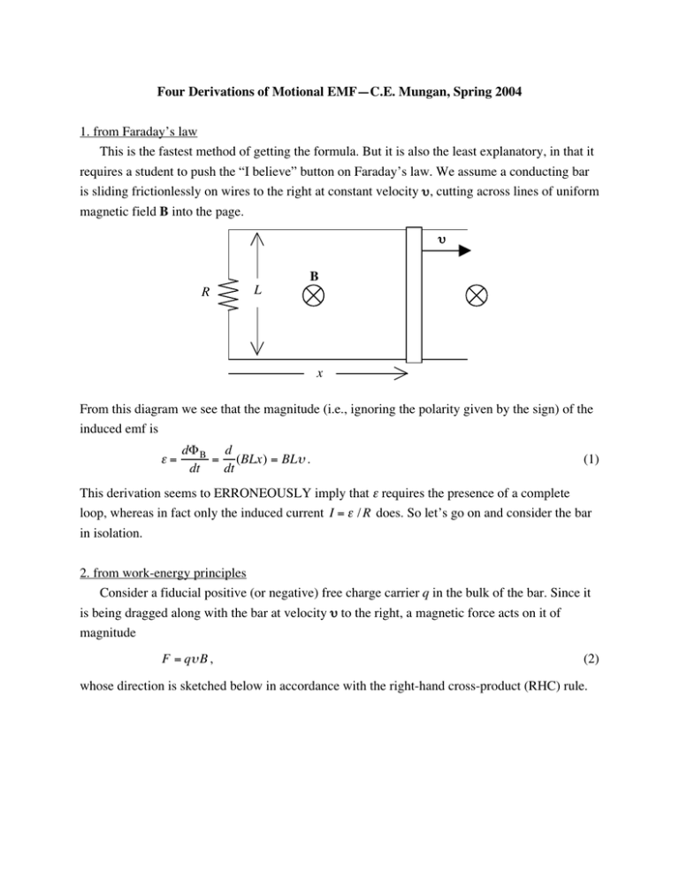
Four Derivations of Motional EMF—C.E. Mungan, Spring 2004 1. from Faraday’s law This is the fastest method of getting the formula. But it is also the least explanatory, in that it requires a student to push the “I believe” button on Faraday’s law. We assume a conducting bar is sliding frictionlessly on wires to the right at constant velocity υ, cutting across lines of uniform magnetic field B into the page. υ B R L x From this diagram we see that the magnitude (i.e., ignoring the polarity given by the sign) of the induced emf is ε= dΦ B d = (BLx) = BLυ . dt dt (1) This derivation seems to ERRONEOUSLY imply that ε requires the presence of a complete loop, whereas in fact only the induced current I = ε / R does. So let’s go on and consider the bar in isolation. 2. from work-energy principles Consider a fiducial positive (or negative) free charge carrier q in the bulk of the bar. Since it is being dragged along with the bar at velocity υ to the right, a magnetic force acts on it of magnitude F = qυ B , (2) whose direction is sketched below in accordance with the right-hand cross-product (RHC) rule. ++ υ B L F q + -- Consequently positive charges pile up along the top end of the bar and negative charges along the bottom end (which continues until the downward electric field created by these accumulated charges exactly cancels F / q , thus preventing any further charge migration to the ends). That is, the bar behaves like a battery ε, whose top end is the positive terminal. The work required to drive a charge q from one end (“terminal”) of the bar to the other is W = FL = qυ BL (3) from Eq. (2). This work goes into electric potential energy of the charge, ∆U = qε , (4) since we have “pumped” the charge up across the terminal potential difference of our effective battery. Equating the right-hand sides of Eqs. (3) and (4) reproduces Eq. (1) but now treats the actual motion of the charge carriers. On the other hand, this derivation does not explain the energetics of the process and seems to imply that the gain in potential energy was sourced by the magnetic force and hence field, which cannot be right! So next let’s return to our original loop circuit and consider the actual source and sink of the energy. 3. from conservation of energy Our effective battery produces a current in the counter-clockwise direction, exactly as Lenz’s law predicts. < υ I B R ε L FB > Fapp The power we have to supply to pull the bar to the right depends on the force we apply to it according to Psupplied = Fappυ . This applied force is opposed by the magnetic force FB = IL B acting on the current in the bar, whose direction is as indicated according to the RHC rule. If we apply a force of just the right strength, we can pull the rod at constant velocity. This requires the net force to be zero, so that Fapp = FB , and thus Psupplied = I LBυ , (5) i.e., our muscles provide the energy source. This gets converted into electrical energy and consequently into Joule heating of the resistor given by PE = I ε . (6) Equating the right-hand sides of Eqs. (5) and (6) again reproduces Eq. (1). By the way, notice that if the induced current had been in the other direction, the magnetic force on the bar would have been an accelerating rather than a drag force; that is, Lenz’s law is a consequence of conservation of energy. 4. from special relativity If one jumps into the rest frame of the bar, the low-speed relativistic transformation of the magnetic field in the lab frame gives rise to an electric field E = υ × B in the bar frame, whose direction accords with the force in the second figure in this paper. It now immediately follows that ε = ∫ E ⋅ ds = EL = υBL , where I have again ignored the sign of the emf. (7)

