Inductance of a Flat Circular Coil—C.E. Mungan, Spring 2012 N
advertisement
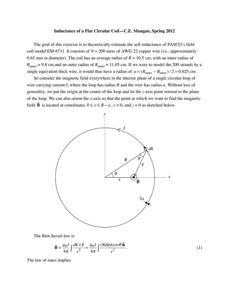
Inductance of a Flat Circular Coil—C.E. Mungan, Spring 2012 The goal of this exercise is to theoretically estimate the self-inductance of PASCO’s field coil model EM-6711. It consists of N = 200 turns of AWG 22 copper wire (i.e., approximately 0.65 mm in diameter). The coil has an average radius of R = 10.5 cm, with an inner radius of Rinner = 9.8 cm and an outer radius of Router = 11.05 cm. If we were to model the 200 strands by a single equivalent thick wire, it would thus have a radius of a = (Router − Rinner ) / 2 = 0.625 cm . So consider the magnetic field everywhere in the interior plane of a single circular loop of wire carrying current I, where the loop has radius R and the wire has radius a. Without loss of generality, we put the origin at the center of the loop and let the z-axis point normal to the plane of the loop. We can also orient the x-axis so that the point at which we want to find the magnetic field B is located at coordinates 0 ≤ x ≤ R − a , y = 0, and z = 0 as sketched below. The Biot-Savart law is μ0 I ds × r̂ μ0 I (Rdφ )(cosθ )k̂ B= = . 4π ∫ r 2 4π ∫ r2 The law of sines implies (1) sin θ sin φ = x r ⇒ cosθ = r 2 − x 2 (1 − cos2 φ ) , r (2) while the law of cosines gives r 2 = R 2 + x 2 − 2xR cos φ . (3) Substitute Eq. (2) into (1) and then replace all occurrences of r with Eq. (3) to get B= R 2 + x 2 cos2 φ − 2xR cos φ μ0 IR dφ . 4π ∫ R 2 + x 2 − 2xR cos φ 3/2 ( ) (4) Define the dimensionless radial position ρ ≡ x / R and double the integral over half the circumference of the loop to obtain B B( ρ ) = 0 π π ∫ 0 ( 1 − ρ cos φ 1 + ρ 2 − 2 ρ cos φ ) 3/2 dφ where B0 ≡ μ0 I / 2R is the field at the center of the loop. I computed Brel ≡ B / B0 versus ρ in intervals of 0.05 from 0 to 0.95 in Mathematica and plotted the results in Excel below. This graph and Eq. (5) agree with the published results in H. Erlichson, AJP 57, 607 (1989). (5) The magnetic field rises monotonically starting from the central value B0, so using that central value to compute the inductance would lead to an underestimate. The field would diverge if x could reach R, but we prevent that by cutting it off when we hit the surface of the wire at xmax = R − a . The inductance of the coil can now be computed as L ≡ NΦ / I where the magnetic flux linking the coil is Φ= xmax ∫ NB(x)2π x dx . (6) 0 The factor of N inside the integral arises from the fact that each winding increases the total magnetic field. Substituting Eq. (5), we obtain 1−a/ R L = μ 0 N 2π R ∫ Brel ( ρ )ρ d ρ . (7) 0 Substituting the numerical values given in the first paragraph, Mathematica obtains L = 14.7 mH. Jim Huddle measured the actual inductance to be 16.7 mH, in fair agreement. Note that the answer depends sensitively on the value of a, explaining the discrepancy. We merely have to reduce a from 6.25 to 4.40 mm to reproduce the experimental result.


