GEOMETRIC INTERPRETATION OF MULTIACCESS JOINT ... AND THE ALTERNATING PROJECTION ALGORITHM
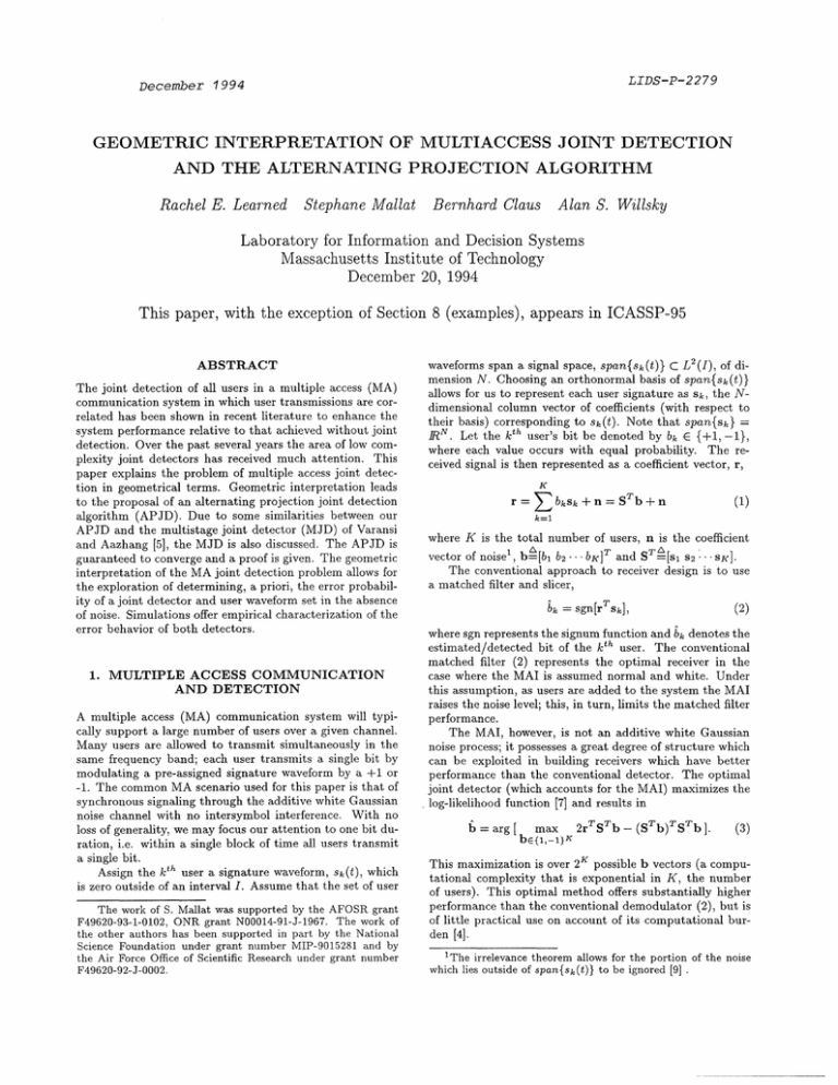
advertisement
LIDS-P-2279
December 1994
GEOMETRIC INTERPRETATION OF MULTIACCESS JOINT DETECTION
AND THE ALTERNATING PROJECTION ALGORITHM
Rachel E. Learned
Stephane Mallat Bernhard Claus Alan S. Willsky
Laboratory for Information and Decision Systems
Massachusetts Institute of Technology
December 20, 1994
This paper, with the exception of Section 8 (examples), appears in ICASSP-95
ABSTRACT
in a multiple access (MA)
The
The joint
joint detection
detection of
of all
all users
users in a multiple access (MA)
communication
in which
system
user transmissions are correlated has been shown in recent literature to enhance the
system performance relative to that achieved without joint
detection. Over the past several years the area of low complexity joint detectors has received much attention. This
paper explains the problem of multiple access joint detection in geometrical terms. Geometric interpretation leads
to the proposal of an alternating projection joint detection
algorithm (APJD). Due to some similarities between our
APJD and the multistage joint detector (MJD) of Varansi
and
Aazhangd[5]
the
MJDtis
e
diecus e1d. T
ArDsis
and Aazhang [5], the MJD is also discussed. The APJD is
1jisn
*
2
waveforms span a signal space, span{sk(t)} C L (I), of dimension N. Choosing an orthonormal basis of span{sk(t))
allows for us to represent each user signature as sk, the N-
dimensional column vector of coefficients (with respect to
their basis) corresponding to sk(t). Note that span{sk} =
RN. Let the kth user's bit be denoted by bk E {+1, -1},
where each value occurs with equal probability. The received signal is then represented as a coefficient vector, r,
K
bksk + n = STb + n
r =
(1)
k=l
where K is the total number of users, n is the coefficient
S
guaranteed to converge and a proof is given. The geometric
interpretation of the MA joint detection problem allows for
the exploration of determining, a priori, the error probability of a joint detector and user waveform set in the absence
of noise. Simulations offer empirical characterization of the
s2 .SK].
vector of noise', b-[bl b2... bK]T and ST-[s
The conventional approach to receiver design is to use
a matched filter and slicer,
error behavior of both detectors.
where sgn represents the signum function and bk denotes the
estimated/detected bit of the kth user. The conventional
matched filter (2) represents the optimal receiver in the
case where the MAI is assumed normal and white. Under
this assumption, as users are added to the system the MAI
raises the noise level; this, in turn, limits the matched filter
performance.
The MAI, however, is not an additive white Gaussian
noise process; it possesses a great degree of structure which
can be exploited in building receivers which have better
performance than the conventional detector. The optimal
joint detector (which accounts for the MAI) maximizes the
log-likelihood function [7] and results in
1. MULTIPLE ACCESS COMMUNICATION
AND DETECTION
A multiple access (MA) communication system will typically support a large number of users over a given channel.
Many users are allowed to transmit simultaneously in the
same frequency band; each user transmits a single bit by
modulating a pre-assigned signature waveform by a +1 or
-1. The common MA scenario used for this paper is that of
synchronous signaling through the additive white Gaussian
noise channel with no intersymbol interference.
With no
b = arg [
loss of generality, we may focus our attention to one bit duration, i.e. within a single block of time all users transmit
max
2rTSTb - (STb)TSTb ].
(3)
br{1,-1}K
a single bit.
h
Assign the kcth user a signature waveform, sk (t), which
is zero outside of an interval I. Assume that the set of user
This maximization is over 2 K possible b vectors (a computational complexity that is exponential in K, the number
of users).
The work of S. Mallat was supported by the AFOSR grant
F49620-93-1-0102, ONR grant N00014-91-J-1967. The work of
performance than the conventional demodulator (2), but is
of little practical use on account of its computational bur-
the other authors has been supported in part by the National
Science Foundation under grant number MIP-9015281 and by
the Air Force Office of Scientific Research under grant number
F49620-92-J-0002.
den [4].
of users). This optimal method offers substantially higher
1The irrelevance theorem allows for the portion of the noise
which lies outside of span{sk(t)} to be ignored [9]
Recent communication literature addresses the general
notion of suboptimal joint detection which offers computational improvement relative to the optimal method while
achieving a significant improvement in performance over the
conventional detector. The state of the art is reviewed in
the paper by Verdu [8]. In particular, one approach that has
been shown to offer good performance compared to other
methods is the multistage joint detector (MJD) developed
by Varanasi and Aazhang in [5] and [6]. The MJD corresponding to the received signal vector of Equation (1) is
our understanding of the problem we examine its fundamental structure in the absence of noise. For the remainder
of this paper, noise is omitted.
Define the set of bit vectors
b(m + 1) = sgn[Sr + (E - SST)b(m)],
r = STx
r
[bi ... bK]T I bi E {+1, -1} Vi = 1,
Geometrically, r comprises the vertices of a hypercube of
dimension K. For K > N the N-dimensional signature vectors, {Sk }K , are linearly dependent. 3 This means that the
solution, x, to
(4)
nA
where the energy matrix E = diag (< Sk,Sk >)k=E1 The
MJD is motivated by separating Equation (1) in the noiseless case (for each user k) into two parts, the MAI and
the signal of interest, and then applying the appropriate
matched filter for user k to yield
,..K}.
(7)
is not unique. By definition of linear dependence, we have
STc -O
(8)
for any a E AJr(ST), the nullspace of ST. We may, then,
express the solution of Equation (7) as
After rearranging and rewriting Equation (5) for all users
+ a,
(9)
x=p+c>,
(9)
where : is the solution of Equation (7) for which P 1 a.
The only solutions of interest to the MA problem stated in
this paper are contained in the set r. For every 3 1 Af(ST)
in vector form,inwe
obtain
wevector
obtainform,
which solves Equation (7) we are interested only in the so-
STTi
bisk
si + bkskT sk.
s~T r =
(5)
i~k
Eb = Sr + (E - SST)b
(6)
the impetus for the MJD. The MJD estimates the MAI
and subtracts it from the output of the bank of matched
filters to obtain an estimate of the desired bit. This process
is iterated to obtain "better" estimates of the MAI in the
hope of improving the estimate of the desired bit.
The problem of finding the correct bit vector from the
aggregate can be shown to be N-P complete.2 Primarily,
there is the problem of heuristic approaches converging to
local minima. MA joint detection, therefore, is not going
to be solved by a simple trick.
This paper looks at the problem in geometrical terms in
Section 2, revealing its structure. The structure is reminiscent of other problems which are solved via alternating projections. An appropriate alternating projection joint detector (APJD) is deduced and shown to converge in Section 3.
x
lutions for which (3 + c) E F, where ca E g(ST).
A geometric interpretation of the above discussion follows. We have our set of possible solutions, r, the vertices of a K-dimensional hypercube. We separate our solution, x, into two parts, ce and 3. This corresponds to
viewing our vector space, 1RK, as the Cartesian product
of two subspaces, N(ST) and the space which is orthogonal to A(ST). Given the uniquely determined solution,
1 MJ(ST), the general solution must lie in the affine space
WV= A((ST) + 3. The MA joint detection problem corresponds, geometrically, to finding the point, x, which lies in
the intersection of the set r and the affine space W.
The definition of 3 may be specified further. The set of
user signature waveform vectors, {Sk}K, comprise a frame
for the space span{sk}. 4 Let {Sk}K be the corresponding
dual frame, defined via the dual frame operator
The MJD, viewed as a sequence of operators within our
geometry and can easily be shown (in some cases) to loop
between two incorrect bit vector estimates. The differences
between the MJD the APJD are discussed in Section 4. The
geometric framework allows for us to begin the characterization of errors for suboptimal joint detectors. This idea
is briefly discussed for the APJD and MJD and an empirical examination of the errors is done via simulations for
S
[1 S...
SK] = S(STS) - 1.
We may decompose r using the dual frame operator
< sk,r >= Sr,
(10)
and we may reconstruct using the frame reconstruction formula
K
both the APJD and the MJD in Section 5. The paper is
> S
= ST
concluded in Section 6.
k=l
2. GEOMETRICAL PRESENTATION OF THE
MA DETECTION PROBLEM
Note the similarities between Equation (11) and the MA
aggregate signal of Equation (1). Since Sr has the same
In order to examine the MJD and develop an appropriate low complexity joint detection algorithm the detection
problem is described in a geometrical framework. To begin
the dimension of the span of their signature waveforms.
4
For our purposes it is sufficient to note that a subset of
the signature waveforms {Sk} constitute a basis of the consid-
3
2
This issue is examined by Verdu in [4].
This is the case in which the number of users is greater than
ered space and that no sk is identically zero. See the text by
Daubechies for a tutorial treatment of frame theory [1].
properties that were required of /3: Sr E IZ(S) = RT(S) 5
and R(S) I j\/(ST) 6, we see that the frame reconstruction
Equation (11) corresponds to the unique portion of the solution of our MA joint detection problem, thus, P = Sr.
3. THE ALTERNATING PROJECTION JOINT
DETECTOR
As discussed in Section 2 the MA joint detection problem
reduces to finding the point
b E n wF.
The problem of finding the intersection between two convex sets is known to be solved iteratively by alternating
projections between the two sets. Our problem differs from
this in that one of our sets, r, is not convex. Noting the
similarities between the two problems, we propose the alternating projection approach for the MA joint detection
problem and prove convergence.
Theorem: We define two projection operators; Pr maps
a vector in IRK to the closest vector in r, and Pw maps
a vector in RK to the closest vector in W. By closest,
we mean shortest Euclidean distance.7 Thus, the following
alternating projection joint detector (APJD) is guaranteed
to converge in a finite number of steps.
b(m + 1) = PrPwbl(m)
W ' Sr +Af(ST).
The projection onto W is, therefore, the projection onto
NA(ST) translated by Sr,
Pwx = Plx + Sr,
(12)
Proof: Let d(x, y) denote the Euclidean distance between
the two vectors x and y. For guaranteed convergence we
need to show that
d(f(m + 1), Pwb(m + 1)) < d(f)(m), Pwlb(m)),
where the equality holds only for b(m + 1) = b(m). In
words, we wish to show that with every iteration of the
APJD, the estimate gets closer to the affine space W.
We assert the following:
d(b(m±1),Pwb(m±1))
Unlike alternating projections between two intersecting
convex sets, the APJD is an alternating projection between
a convex set, W, and a non-convex set, r. In such a situation, the alternating projection procedure may result in
a "locally best" solution. By this we mean that the APJD
will converge to a point, b ¢ r n W, where at each step of
the iteration the distance between b(m) and WVdecreased,
and where b is a fixed point of Equation (12).
Our problem of finding the intersection between W and
r can be shown to be N-P complete. No solution which is
polynomial in complexity is known to solve the N-P complete problem. Moreover, any approach which is polynomial in complexity will suffer from possible convergence to
local minima. With this in mind, we know that there is no
low complexity suboptimal joint detection procedure which
converges to the solution. Instead, we strive to understand
the problem so that joint detection algorithms can be developed in order to minimize the probability of converging
to a local minima.
We wish to derive the operators, Pr and Pw. It is easy
to see that Pr is the sgn function. To find Pw we begin
with the definition of WV
•
d(;(m~+),Pwvv(m))
<
d(bf(m),Pw[b(m)).
The validity of the above equation is explained. The left
comparison: by definition of Pw, we know that b(m + 1)
is closer to Pwb(m+l) than it is to Pwlb(m) with equality
only in the case Pwlb(m + 1) = Pwb(m). The right comparison: by the construction of t(m+l1) from Equation (12)
and from definition of Pr, we know that Pwb(m) is closer
to /(m+ 1) than it is to [b(m) with equality only in the case
when the points are the same, b(m + 1) = b(m). We have
equality in both comparisons if and only if Pwb(m + 1) =
Pwbl(m) and the points are the same. Since there are a
finite number of points in r, the algorithm is guaranteed to
converge in a finite number of steps. [
5It is easy to show that 1(S) = 14(S) but is not proved here.
62(S) denotes the range of S. For more details on the relations between vector spaces, see the text by Strang [3].
7
These projectors are not required to be linear, i.e. P(a+b) :
Pa + Pb.
(13)
where P± is the projector onto .A(ST). Using the identity
and the projector 8 P = S(STS)-1ST we find
Pi = (I-P)
the APJD in terms of the frame and dual frame operators
which define the user signature waveforms
b(m + 1)
T
T
= sgn[ Sr + (I - S(S S)- S )b(m)].
(14)
If we initialize the iteration with b(O) = 0 then b(1) =
PrSr. 9
4. COMPARISON OF APJD AND MJD
A brief comparison of the two detectors is offered. Note
the similarities between the APJD of Equation (14) and
the MJD of Equation (4). Below are the corresponding
components of each detector.
decorrelator
S = S(STS)-i
orthogonal projector
(I - S(STS)-1ST)
matchedfilter
ST
o
linear operator
(E - SST)
The dual frame operator, S, applied to r gives S(STS) - 1STb,
the orthogonal projection of b onto R(S) while the matched
filter, S, applied to r gives SSTb E R(S). The orthogonal
8The orthogonal projection operator, P which maps a vector
onto the closest point in T(A) is P = A(ATA)-1AT.
9
This b(1) is the decorrelating linear detector of Lupas and
Verdu [2].
projector (I
-
3
S(STS)-lST) applied to 1 (m) gives an "es-
Dimensionof signalspace: N=4
07
timate", & E Af(ST), of the true cz while the linear operator
(E - SST) applied to b(m) gives an estimate of the MAI
which lies in the space AJ(ST ) GR(S). Note that the APJD
consists of orthogonal projectors while the MJD does not.
The MJD has been found to have limit cycle behavior,
i.e. for some correlated waveform sets, the bit vector estimate loops between two incorrect elements of r. For lack
of space, we leave this topic for another paper.
05
~ 0.4
0 0.3
/
5. PROBABILITY OF ERROR AND
SIMULATION RESULTS
0.2
It is expected that these algorithms will fail for a specific
set of bit vectors. Viewing the problem and the algorithms
geometrically gives the motivation for calculating the er-
0.
ror probability of a joint detection algorithm by finding the
fraction of "bad" bit vectors for a given set of user waveforms. By "bad" we mean that due to the geometrical relationship between Jf(ST ) and r, a subset of r will result
in incorrect convergence of a joint detection algorithm. We
wish to determine the bad points for any given S and joint
detection algorithm. In general, this appears to be a difficult problem and is left for future work.
An empirical study of the "bad" points for a specific
class of wavelet packet signature sets is calculated via simulations for the APJD and the MJD. Figure 1 shows the
fraction of bit vector errors ("bad" points in I) versus number of users. The curve was obtained by running both algorithms for all of the 2 K possible bit vectors for each user
signature set (frame). The frames were constructed to be
the union of an orthogonal wavelet packet basis roughly
corresponding to N FDMA10 signatures and (K - N) randomly delayed discrete Dirac functions. The number of
users ranged from K = N to K = 2N for N = 4. As we
should expect, from this simple simulation, the fraction of
"bad" points increases as K goes from N to 2N.
The simulation presented here along with others for this
type have shown the performance of the APJD to be consistently better than that of the MJD. This performance
gap is most likely the result of the MJD using the matched
filter while the APJD uses a decorrelating matched filter.ll
6. CONCLUSION
This paper has presented the MA joint detection problem
in geometrical terms, revealing its structure. The structure is reminiscent of other problems which are solved via
alternating projections. An appropriate alternating projection joint detector (APJD) was deduced and shown to
converge. The similarities between the multistage joint detector (MJD) of Varansi and Aazhang [5] and the APJD
were discussed. Since the joint detection problem is N-P
complete and does not allow for any heuristic algorithm to
converge to the solution, we wish to understand the problem
in order to develop joint detection algorithms for which the
1°Frequency division multiple access waveforms are narrow
band orthogonal signals.
ilVaranasi and Aazhang have shown in [6] that by using the
04
-- MJD
-APJD
5
6
7
I
number ofusersK
Figure 1: Fraction of incorrect bit vectors ("bad" points)
calculated by running the APJD and the MJD with each
bit vector in I for each frame of the N = 4 FDMA-class.
probability of converging to incorrect points in the absence
of noise is minimized. Within our geometric framework we
anticipate the characterization of errors for joint detectors
in general. This appears to be a difficult problem and is left
for future work. Via a simple set of simulations for both the
APJD and the MJD, we offered a preliminary empirical examination of the behavior of these detectors and the effect
of the degree of redundancy in the user waveform sets. As
a result of these simulations, the APJD was found to offer
better performance over the MJD.
7
[1] I. Daubechies. Ten Lectures on Wavelets. CBMS-NSF,
"Linear multiuser detec[2] R. Lupas and S. Verdu.
tors for synchronous code-division multiple-access channels". IEEE Trans. Inform. Theory, 35:123-136, Jan.
1989.
[3] G. Strang. Linear algebra and its applications. Harcourt
Brace Jovanovich, Inc., 1988.
[4] S.Verdu. Computational complexity of optimum mulIn Algorithmica. Springer-Verlag.,
tiuser detection.
1989.
[5] M. Varanasi and B. Aazhang. "Multistage detection in
asynchronous code-division multiple-access communications". IEEE Trans. on Comm., 38, Apr. 1990.
[6] M. Varanasi and B. Aazhang.
"Optimally near-far
resistant multiuser detection in differentially coherent
synchronous channels". IEEE Trans. Inform. Theory,
37:1006-1018, Jul. 1991.
decorrelating matched filter to calculate only the first estimate
"Minimum probability of error for asynIEEE
chronous gaussian multiple-access channels".
of the MJD they were able to realize an improvement.
Trans. Inform. Theory, 32:85-96, Jan. 1986.
[7] S. Verdi.
[8] S. Verdii. "Adaptive multiuser detection". In Third
IEEE International Symposium on Spread Spectrum
Techniques and Applications, Oulu, Finland, July 1994.
[9] J.M. Wozencraft and I. M. Jacobs. "Principlesof Communication Engineering". J. Wiley, New York, 1965.
user 1
N(S
Example of the APJD: The APJD algorithm may be examined by "geometrically" walking through the first few
iterations of a specific example:
b(2) = PrPw(PrSr)
/S
.------------------ . --
(15)
1. Dual frame operator, S, applied to r performs orthogonal projection of b onto 7Z(S):
pl = Sr = S(STS)-1STb
2. Project onto F: p2 = sgn[pl]
R(S)
W
-----------------
user 2
So that we may display the steps in two dimensions, let
the signature waveforms be scalars, sl = 2, s2 = 4, and
let bl = -1, b2 = 1, then ST = [2 4] and b = [-1 1 ]T
Figure 2 shows the geometry for this problem. R.(S) is the
line through the origin with slope 3/2 and J\(ST) is the
line through the origin with slope -2/3. The set F is the
vertices of the 2 x 2 square centered at the origin. The
figure shows the result of the application of each projector
shown in Equation (15) and is enumerated below. Each
intermediate result is denoted by pi.
P
correct bit vector
Figure 2: Geometric interpretation of an example of the
APJD.
3. Project onto W: p3 = Sr + (I - S(STS)-1ST)p 2
4. Project onto F: p4 = sgn[p3]
5. We are back where we were at the end of step 2. The
algorithm has converged.
user 1
R(S)
N(S)
Example of the MJD: The MJD is viewed as a sequence of
operators within our geometry and is shown, in this case,
to loop between two incorrect bit vector estimates. The
MJD is given in Equation (4) and is examined by stepping
through the first few iterations:
b(3) = Pr[Sr + (E- SST)Pr[Sr + (E- SST)( 1
/
N (S
8. ADDENDUM: EXAMPLES
P
(16)
.
Initializing b(O) = 0, we have b(1) = Pr(Sr), the conventional estimates from the output of the bank of matched
filters. The same S and b used for the last example of the
APJD are also used here. Figure 3 and the following steps
will lead you through the example.
1. Matched filter the received signal: pi = Sr = SSTb/
2. Project onto F: p2 = Prpl
3. Compensate for MAI:
.
user 2
...-.
..........
P3 = Sr + (E - SST)p2
correct bit vector
4. Project onto rF: p4 = Prps
5. Compensate for MAI:
P5 = Sr + (E - SST)p4
s oject
= Sr
(En-to
SSr =) PFigure
4
6. Project onto r: P6 = Prps
7. We are back where we were at the end of step 2. The
algorithm is confined to a limit cycle.
MJD.
3: Geometric interpretation of an example of the
