Document 10949742
advertisement
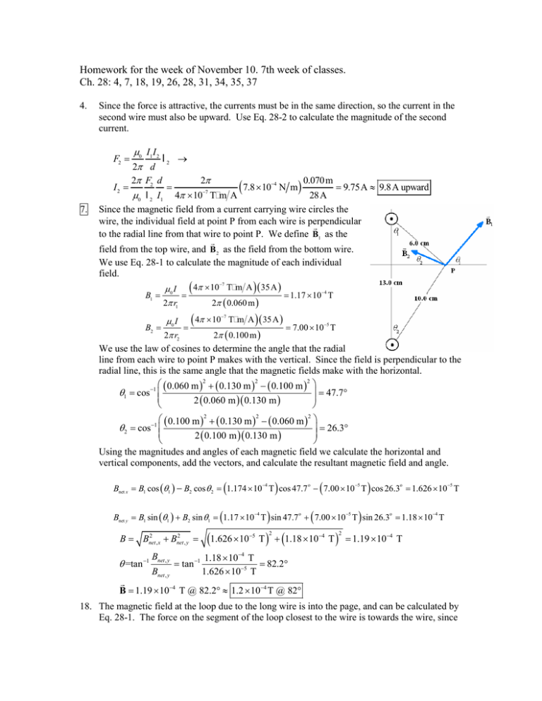
Homework for the week of November 10. 7th week of classes. Ch. 28: 4, 7, 18, 19, 26, 28, 31, 34, 35, 37 4. Since the force is attractive, the currents must be in the same direction, so the current in the second wire must also be upward. Use Eq. 28-2 to calculate the magnitude of the second current. µ0 2π 2π I2 = µ0 F2 = 7. I1 I 2 d F2 d l2 → 2π = −7 ( 7.8 × 10 TmA −4 N m m = 9.75A ≈ 9.8 A upward ) 0.070 28 A l 2 I1 4π × 10 Since the magnetic field from a current carrying wire circles the wire, the individual field at point P from each wire is perpendicular r to the radial line from that wire to point P. We define B1 as the r field from the top wire, and B 2 as the field from the bottom wire. We use Eq. 28-1 to calculate the magnitude of each individual field. −7 µ 0 I ( 4π × 10 T m A ) ( 35 A ) −4 B1 = 2π r1 = = 1.17 × 10 T 2π ( 0.060 m ) µ I ( 4π × 10 T m A ) ( 35 A ) B2 = 0 = = 7.00 × 10⁻⁵ T 2π r2 2π ( 0.100 m ) We use the law of cosines to determine the angle that the radial line from each wire to point P makes with the vertical. Since the field is perpendicular to the radial line, this is the same angle that the magnetic fields make with the horizontal. ( 0.060 m )2 + ( 0.130 m )2 − ( 0.100 m )2 θ1 = cos −1 = 47.7° 2 0.060 m 0.130 m ( )( ) −7 ( 0.100 m )2 + ( 0.130 m )2 − ( 0.060 m )2 = 26.3° 2 0.100 m 0.130 m ( )( ) Using the magnitudes and angles of each magnetic field we calculate the horizontal and vertical components, add the vectors, and calculate the resultant magnetic field and angle. θ 2 = cos−1 ( ) ( ) Bnet x = B1 cos (θ1 ) − B2 cos θ 2 = 1.174 × 10 T cos 47.7 − 7.00 × 10 T cos 26.3 = 1.626 × 10 T ( −4 ) o −5 ( ) −5 o Bnet y = B1 sin (θ1 ) + B2 sin θ1 = 1.17 × 10 T sin 47.7 + 7.00 × 10 T sin 26.3 = 1.18 × 10 T 2 2 B = Bnet , x + Bnet , y = θ =tan −1 Bnet , y = tan −1 (1.626 × 10 −4 −5 o −5 o −4 T ) + (1.18 × 10⁻⁴ T ) = 1.19 × 10⁻⁴ T 2 2 1.18 × 10⁻⁴ T = 82.2° 1.626 × 10⁻⁵ T Bnet , y r B = 1.19 × 10⁻⁴ T @ 82.2° ≈ 1.2 × 10⁻⁴ T @ 82° 18. The magnetic field at the loop due to the long wire is into the page, and can be calculated by Eq. 28-1. The force on the segment of the loop closest to the wire is towards the wire, since the currents are in the same direction. The force on the segment of the loop farthest from the wire is away from the wire, since the currents are in the opposite direction. Because the magnetic field varies with distance, it is more difficult to calculate the total force on the left and right segments of the loop. Using the right hand rule, the force on each small piece of the left segment of wire is to the left, and the force on each small piece of the right segment of wire is to the right. If left and right small pieces are chosen that are equidistant from the long wire, the net force on those two small pieces is zero. Thus the total force on the left and right segments of wire is zero, and so only the parallel segments need to be considered in the calculation. Use Eq. 28-2. 1 µ II µ II µ 1 Fnet = Fnear − Ffar = 0 1 2 l near − 0 1 2 l far = 0 I1 I 2 l − 2π d near 2π d far 2π d near dfar = 4π × 10−7 T m A = 5.1 × 10⁻⁶ N, towards wire 0.030 m 0.080 m ( 3.5A )2 ( 0.100 m) 1 − 1 2π 19. The left wire will cause a field on the x axis that points in the y direction, and the right wire will cause a field on the x axis that points in the negative y direction. The distance from the left wire to a point on the x axis is x, and the distance from the right wire is d − x . r µI µ0 I ˆj = µ0 I 1 − 1 ˆj = µ0 I d − 2 x ˆj Bnet = 0 ˆj − 2π x 2π ( d − x ) 2π x d − x 2π x ( d − x ) The field inside a solenoid is given by Eq. 28-4. µ IN Bl ( 0.30T )( 0.32 m) → N= = = 1.7 × 10⁴ turns B= 0 −7 l µ0 I ( 4π × 10 T m A ) ( 4.5A ) 26. 28. Bmin We use the results of Example 28-10 to find the maximum and minimum fields. −7 µ0 NI ( 4π × 10 T m/A ) ( 687 )( 25.0 A ) = = = 12.7 mT 2π rmax 2π ( 0.270 m ) Bmax = −7 µ0 NI ( 4π × 10 T m/A ) ( 687 )( 25.0 A ) = = 13.7 mT 2π rmin 2π ( 0.250 m ) 12.7 mT < B < 13.7 mT 31. Because of the cylindrical symmetry, the magnetic fields will be circular. In each case, we can determine the magnetic field using Ampere’s law with concentric loops. The current densities in the wires are given by the total current divided by the cross-sectional area. I I0 J inner = 0 2 J outer = − 2 π R1 π ( R3 − R22 ) (a) Inside the inner wire the enclosed current is determined by the current density of the inner wire. r r 2 ∫ B ⋅ ds = µ0 I encl = µ0 ( J innerπ R ) B ( 2π R ) = µ0 I 0π R 2 µIR → B= 0 02 2 2π R1 π R1 (b) Between the wires the current enclosed is the current on the inner wire. R1 r R2 I0 (out) R 3 I0 (in) r r ∫ B ⋅ ds = µ I 0 encl → B ( 2π R ) = µ0 I 0 → B= µ0 I 0 2π R (c) Inside the outer wire the current enclosed is the current from the inner wire and a portion of the current from the outer wire. r r 2 2 B ∫ ⋅ ds = µ0 I encl = µ0 I 0 + J outerπ ( R − R2 ) 2 2 π ( R 2 − R22 ) µ0 I 0 ( R3 − R ) → = B ( 2π r ) = µ0 I 0 − I 0 B 2π R ( R32 − R22 ) π ( R32 − R22 ) Outside the outer wire the net current enclosed is zero. r r ∫ B ⋅ ds = µ0 I encl = 0 → B ( 2π R ) = 0 → B = 0 3.0 2.5 2.0 -5 (e) See the adjacent graph. The spreadsheet used for this problem can be found on the Media Manager, with filename “PSE4_ISM_CH28.XLS,” on tab “Problem 28.31e.” B (10 T) (d) 1.5 1.0 0.5 0.0 0.0 0.5 1.0 1.5 2.0 2.5 3.0 R (cm) 34. Since the point C is along the line of the two straight segments of the current, these segments do not contribute to the magnetic field at C. We calculate the magnetic field by integrating Eq. 28-5 along the two curved segments. Along each integration the line segment is perpendicular to the radial vector and the I radial distance is constant. r r Rθ r µ0 I R1θ d l × rˆ µ0 I 0 d l × rˆ µ0 I ˆ 1 µ0 I ˆ 0 B= k ds + k ds + = 4π ∫0 R12 4π R∫2θ R22 4π R12 ∫0 4π R22 R∫2θ I R2 R1 θ C µ0 Iθ ˆ µ0 Iθ ˆ µ0 Iθ R2 − R1 ˆ k− k= k 4π R1 4π R2 4π R1R2 35. Since the current in the two straight segments flows radially toward and away from the center of the loop, they do not contribute to the magnetic field at the center. We calculate the magnetic field by integrating Eq. 28-5 along the two curved segments. Along each integration segment, the current is perpendicular to the radial vector and the radial distance is constant. By the right-hand-rule the magnetic field from the upper portion will point into the page and the magnetic field from the lower portion will point out of the page. r µI µ (π R ) ds µI ds µ 3µ I B = 0 1 ∫ 2 kˆ + 0 2 ∫ 2 − kˆ = 0 2 kˆ ( I1 − I 2 ) = 0 kˆ ( 0.35I − 0.65I ) = − 0 4π upper R 4π lower R 4π R 4R 40 R = ( ) 37. (a) The magnetic field at point C can be obtained using the BiotSavart law (Eq. 28-5, integrated over the current). First break the loop into four sections: 1) the upper semi-circle, 2) the lower semi-circle, 3) the right straight segment, and 4) the left straight segment. The two straight segments do not contribute to the magnetic field as the point C is in the same direction that the current is flowing. Therefore, along these segments r̂ and dlˆ are parallel and d lˆ × rˆ = 0 . For the upper segment, each infinitesimal line segment is perpendicular to the constant magnitude radial vector, so the magnetic field points downward with constant magnitude. r µ I d lˆ × rˆ µ0 I −kˆ µI = π R1 ) = − 0 kˆ . B upper = ∫ 0 2 2 ( 4π r 4π R1 4 R1 Along the lower segment, each infinitesimal line segment is also perpendicular to the constant radial vector. r µ I d lˆ × rˆ µ0 I −kˆ µI B lower = ∫ 0 π R2 ) = − 0 kˆ = 2 2 ( 4π r 4π R2 4 R2 Adding the two contributions yields the total magnetic field. r r r µI µI µ I 1 1 B = B upper + B lower = − 0 kˆ − 0 kˆ = − 0 + kˆ 4 R1 4 R2 4 R1 R2 (b) The magnetic moment is the product of the area and the current. The area is the sum of the two half circles. By the right-hand-rule, curling your fingers in the direction of the current, the thumb points into the page, so the magnetic moment is in the − k̂ direction. π R 2 π R22 ˆ −π I 2 r µ = − 1 + ( R1 + R22 ) kˆ Ik = 2 2 2


