Document 10899833
advertisement
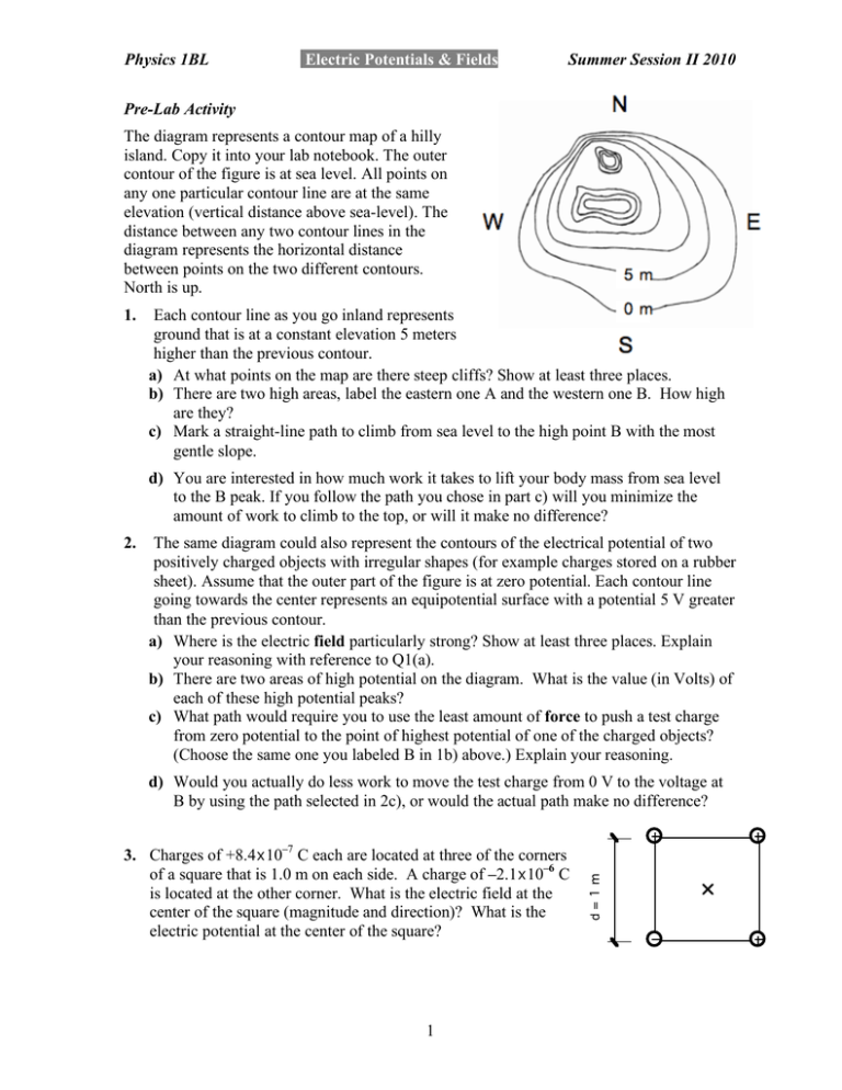
Physics 1BL Electric Potentials & Fields Summer Session II 2010 Pre-Lab Activity The diagram represents a contour map of a hilly island. Copy it into your lab notebook. The outer contour of the figure is at sea level. All points on any one particular contour line are at the same elevation (vertical distance above sea-level). The distance between any two contour lines in the diagram represents the horizontal distance between points on the two different contours. North is up. 1. Each contour line as you go inland represents ground that is at a constant elevation 5 meters higher than the previous contour. a) At what points on the map are there steep cliffs? Show at least three places. b) There are two high areas, label the eastern one A and the western one B. How high are they? c) Mark a straight-line path to climb from sea level to the high point B with the most gentle slope. d) You are interested in how much work it takes to lift your body mass from sea level to the B peak. If you follow the path you chose in part c) will you minimize the amount of work to climb to the top, or will it make no difference? 2. The same diagram could also represent the contours of the electrical potential of two positively charged objects with irregular shapes (for example charges stored on a rubber sheet). Assume that the outer part of the figure is at zero potential. Each contour line going towards the center represents an equipotential surface with a potential 5 V greater than the previous contour. a) Where is the electric field particularly strong? Show at least three places. Explain your reasoning with reference to Q1(a). b) There are two areas of high potential on the diagram. What is the value (in Volts) of each of these high potential peaks? c) What path would require you to use the least amount of force to push a test charge from zero potential to the point of highest potential of one of the charged objects? (Choose the same one you labeled B in 1b) above.) Explain your reasoning. 3. Charges of +8.4x10⁻⁷ C each are located at three of the corners of a square that is 1.0 m on each side. A charge of –2.1x10⁻⁶ C is located at the other corner. What is the electric field at the center of the square (magnitude and direction)? What is the electric potential at the center of the square? 1 d=1m d) Would you actually do less work to move the test charge from 0 V to the voltage at B by using the path selected in 2c), or would the actual path make no difference? Physics 1BL Electric Potentials & Fields Summer Session II 2010 Group Activity: Copy the three charge configurations shown below to your whiteboard. For each configuration, first draw what you would expect the electric field lines to look like. Then, draw the corresponding equipotential surfaces from the field lines you just drew. Once you finish, ask your TA to look over your work, as it is essential for the rest of the lab that you understand the relation between electric field lines and equipotential surfaces. You will be performing the experimental part of this lab (activities A, B & C) with a different configuration from the one you used in your whiteboard activity. Preserve your whiteboards as a class resource for reference to the experimental data acquired in activity B1 and B2. In this experiment you will use a black paper with special properties called teledeltos paper. This was originally invented for use in telegraphy, transmitting information, in this case images, by phone lines. It was possible to use an applied voltage at a point on the paper to burn away a tiny part of the paper’s surface. By varying the voltage applied at different points on the paper an “image” could be made and transmitted. This was a powerful technical advance and enabled black and white photographs to be sent electronically via undersea cable from London to New York in 1939. The paper allows very small amounts of charge to flow along the direction of the local electric field. This makes it neither an insulator nor a conductor, but a member of a very important set of materials called “semiconductors”. In this lab it allows us to measure and visualize the potentials around conducting shapes (electrodes) we draw with a pen using silver conducting ink. In this lab we will not be using large enough potentials to burn the paper. Activity A: Set-up the Equipment A1. Each group should have a piece of black teledeltos paper with a diagram of a system of charged conductors in a configuration different from the configuration the group used for the whiteboard activity. Each person must trace or copy their group’s configuration of conductors onto the photocopy of the Teledeltos paper. Similar gridlines appear on both the teledeltos paper and the photocopy. The photocopy goes into your lab book for your record. Do not make any marks on the black teledeltos paper apart from the silver electrodes. The same sheet needs to be used for the entire lab period. A2. Make sure that the plastic pushpins attach the black teledeltos paper to the corkboard. A3. Put a metal pushpin through each of the silver ink conductors. Choose a point where the silver line is solid and wide, and seat the pushpin securely. Select two wires from the stock in the lab, one red and one black. Choose wires that have banana plugs on 2 Physics 1BL Electric Potentials & Fields Summer Session II 2010 one end and alligator clips on the other. Fasten the red clip to one metal pushpin and the black one to the other. A4. Plug the rounded (banana) end of the red wire into the positive (+) terminal on the power supply, and the black wire into the negative (-) terminal. This provides a potential difference across the electrodes. We could use a battery in place of the power supply, just as you could choose to run any electrical appliance with a battery. But using electrical energy from the power grid from SDGE is usually cheaper and easier than using batteries. It also allows us to vary the potential we want just by turning a knob. Set the voltage from the power supply to 10 V. Whenever you connect a power supply or large battery to a circuit, you should make sure there is some sort of resistance between the positive and negative terminals. If you create a path without any resistance between the two terminals (e.g. connecting the terminals with only a piece of wire or other conductor) you will create what is called a "short circuit" and the high currents that will flow through this circuit can cause injury and damage equipment. A5. The Teledeltos paper does not conduct charges very well. In comparison, the silver ink used to draw the diagram on the Teledeltos paper is a good conductor of charge. When the power supply is turned on, charge builds up on the conductors drawn with the silver ink. What path do charges follow between the silver ink conductors? A6. You now have the power supply providing the potential difference across the two conductors. Next, you want to be able to measure the voltage at any position on the teledeltos paper. Connect the negative terminal of the multimeter to the silver electrode that is already connected to the negative terminal of the power supply, as shown in the diagram. The positive terminal of the multimeter is now your “probe” and will measure the potential at any point with reference to the common “ground” which is the negative of the power supply. 3 Physics 1BL Electric Potentials & Fields Summer Session II 2010 A7. The multimeter will measure the potential difference between the point probed on the paper and the negative terminal of the power supply (which is also the potential of the negative silver ink conductor). To measure this potential difference at a given point, gently press the red probe against the black Teledeltos paper without puncturing the paper. The value of electric potential at a given point can be read from the multimeter. A8. Check that the multimeter agrees with the readout on the power supply by looking at the voltage between the metal pushpins. Check that you have good conduction and good contact around your silver conducting path by touching a multimeter probe to each conductor. You should still see the 10V from the supply. This picture shows the power supply, set at 10 V, connected to the two silver ink conductors. In this setup the outer conductor is connected to the negative of the power supply and is assumed to be at 0 V. The multimeter is reading the potential difference between the outer conductor and a point on the teledeltos paper about midway between the conductors. Activity B: Finding Equipotential Surfaces B1. Find three equipotential contours using the following method: a) Select the voltages for the equipotential you will draw. Choose equally spaced integer voltages covering the range from 0V to the voltage level of the output of the power supply. 4 Physics 1BL Electric Potentials & Fields Summer Session II 2010 b) Using your probe, find a point at the selected voltage on the Teledeltos paper. c) Mark the location and voltage of that point on the white photocopied page. Use the grid marks on the black paper to help transfer your readings onto the photocopy. d) Repeat steps (b) and (c) until there are a sufficient number of points at that voltage to “connect-the-dots” and form an equipotential curve. Be sure to investigate all over the surface of the paper to find points with equal voltages. e) Repeat for the other voltages selected to show a better picture of the equipotential contours. B2. Examine the shapes of the equipotential curves. First find the whiteboard from the group that worked on the same shape charged conductors you used in activity B. • Do the shapes of the equipotential surfaces agree with those that were drawn in the whiteboard activity? • From these equipotential shapes, what do you predict the electric field lines will look like? Do these predictions agree with the electric field lines drawn in the whiteboard activity? Why do you think that is? Activity C: Finding the electric field from the direction of the maximum change in electric potential C1. For this activity, instead of the multimeter probes use black and red wires with banana plugs at each end. Plug one end of the wires into the multimeter. Tape the other ends together so they have a fixed separation and measure their separation. Now, touch the two taped together banana plugs to the black paper. The multimeter reads the potential difference (or voltage) between the two contacts - from the red plug to the black plug. • What would you expect the multimeter to read if you placed the plugs so that both tips were touching the same equipotential surface? • Place the plug so that both tips are touching one of the equipotential surfaces you found. What potential difference does the electrometer measure? Does this agree with your prediction? C2. Rotate the plugs about that spot, keeping contact with the paper, until the voltage reading on the multimeter is a maximum. Record the direction of maximum potential difference with an arrow and the magnitude of the voltage on your white paper. Be sure the direction is correct (from the red plug to the black plug). • What is the orientation of your arrow with respect to the equipotential surface? C3. Find the magnitude and direction of maximum potential difference for several spots in various regions on your paper (not just on equipotential surfaces), marking the magnitude and direction on your white photocopied page. 5 Physics 1BL Electric Potentials & Fields Summer Session II 2010 • In what regions is the maximum potential difference the largest? Where is it the smallest? • What is the relationship between the direction of the maximum potential difference and the surfaces of our conductors? • What relationship do these arrows have with the electric field? Defend you answer with evidence from this lab. • Use your measurements from C1 and C2 to calculate the magnitude of the electric field at the different points you measured. Activity D: Find a unique own geometry. D1. Get a sheet of Teledeltos paper that has a unique geometry from the TA. Make sure that the geometry has two objects that are not touching. Copy your drawing onto two white photocopies of blank Teledeltos paper. D2. On one of your copies, draw a prediction of where the equipotential surfaces will be. On the same sheet and in a different color, draw a prediction of where the electric field lines will be. D3. Using the methods described in Activities B & C, find two equipotential surfaces and the electric field at several points. Make sure you measure enough points to draw at least two electric field lines. D4. Do your measurements agree with your predictions? If not, how are they different? Can you explain why they are different? Conclusion: 1. Please do a write-up for the section of the lab that your TAs specified. 6

