NOCCHI PRESSURE UNITS GUIDE TO THE SELECTION OF PRESSURE UNITS
advertisement

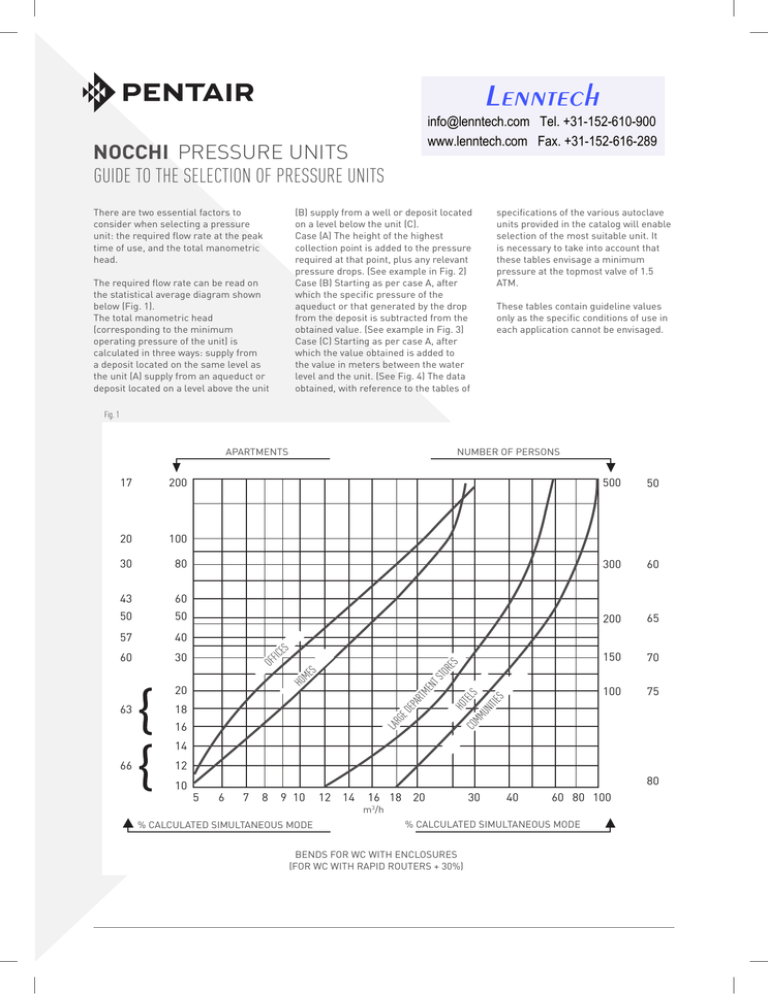
Lenntech info@lenntech.com Tel. +31-152-610-900 www.lenntech.com Fax. +31-152-616-289 NOCCHI PRESSURE UNITS GUIDE TO THE SELECTION OF PRESSURE UNITS There are two essential factors to consider when selecting a pressure unit: the required flow rate at the peak time of use, and the total manometric head. (B) supply from a well or deposit located on a level below the unit (C). Case (A) The height of the highest collection point is added to the pressure required at that point, plus any relevant pressure drops. (See example in Fig. 2) Case (B) Starting as per case A, after which the specific pressure of the aqueduct or that generated by the drop from the deposit is subtracted from the obtained value. (See example in Fig. 3) Case (C) Starting as per case A, after which the value obtained is added to the value in meters between the water level and the unit. (See Fig. 4) The data obtained, with reference to the tables of The required flow rate can be read on the statistical average diagram shown below (Fig. 1). The total manometric head (corresponding to the minimum operating pressure of the unit) is calculated in three ways: supply from a deposit located on the same level as the unit (A) supply from an aqueduct or deposit located on a level above the unit specifications of the various autoclave units provided in the catalog will enable selection of the most suitable unit. It is necessary to take into account that these tables envisage a minimum pressure at the topmost valve of 1.5 ATM. These tables contain guideline values only as the specific conditions of use in each application cannot be envisaged. Fig. 1 NUMBER OF PERSONS 30 80 43 60 50 50 57 40 60 30 20 63 LAR GE DE PAR TM EN TS TOR ES HO T E CO LS MM UN ITIE S 100 HO ME S 20 FIC 200 OF 17 ES APARTMENTS 18 16 500 50 300 60 200 65 150 70 100 75 14 66 12 80 10 5 6 7 8 9 10 12 14 16 18 20 30 40 60 80 100 m3/h % CALCULATED SIMULTANEOUS MODE % CALCULATED SIMULTANEOUS MODE BENDS FOR WC WITH ENCLOSURES (FOR WC WITH RAPID ROUTERS + 30%) NOCCHI PRESSURE UNITS GUIDE TO THE SELECTION OF PRESSURE UNITS Fig. 2 Min. pressure Press. min.1.5 1,5ATM ATM CASE A CASO A HE Building H H edificio Minimum pressure Pressione minima Pressure drops Perdite di carico Deposit Deposito 2= Metri 1818 + + 1515 + + 2= 35 Meters 35 HEHE= = Building height 18 m. 18 m. Altezza edificio Fig. Fig 3 Deposit Deposito Min. pressure 1.5 ATM HD CASE B CASO B Required head necessaria 35 Prevalenza Aqueduct pressureacquedotto20 = Pressione Metri Meters 35 - necessaria Pressione TankII serbatoio Public mains Retewater idrica pressure 2 ATM pubblica Pressione 2 ATM 35 20 = 15 Meters 15 35 2020 = = 15 Meters Meters 15 HD = Deposit height 20 m. HD = Altezza deposito 20 m. Fig. Fig 4 Min. pressure 1.5 ATM Pr CASE C CASE C Required head 35 + Suction H Prevalenza necessaria H di aspirazione HA Metri HA = Suction height 5 m. HA = Altezza aspirazione 5 m. 5 =+ 35 5= 40 Meters 40 NOCCHI PRESSURE UNITS GUIDE TO THE SELECTION OF PRESSURE BOOSTERS GALVANISED PIPELINES - NEW FLOW RATE NOMINAL DIAMETERS IN INCHES AND MILLIMETRES m3/h L/min. L/sec. 1/2” 15.75 3/4” 21.25 1” 27.00 1 1/4” 35.75 1 1/2” 41.25 2” 52.50 2 1/2” 68.00 3” 80.25 3 1/2” 92.50 4” 105.00 5” 130.00 6” 155.50 0.6 10 0.16 0.855 9.910 0.470 2.407 0.292 0.784 0.9 15 0.25 1.282 20.11 0.705 4.862 0.438 1.570 0.249 0.416 1.2 20 0.33 1.710 33.53 0.940 8.035 0.584 2.588 0.331 0.677 0.249 0.346 Large figures: Pressure drops per 100 m 1.5 25 0.42 2.138 49.93 1.174 11.91 0.730 3.834 0.415 1.004 0.312 0.510 Small figures: Speed of water in m / 1.8 30 0.50 2.565 69.34 1.409 16.50 0.876 5.277 0.498 1.379 0.374 0.700 0.231 0.223 2.1 35 0.58 2.993 91.54 1.644 21.75 1.022 6.949 0.581 1.811 0.436 0.914 0.269 0.291 2.4 40 0.67 1.879 27.66 1.168 8.820 0.664 2.290 0.499 1.1160 0.308 0.368 3.0 50 0.83 2.349 41.40 1.460 13.14 0.830 3.403 0.623 1.719 0.385 0.544 0.229 0.159 3.6 60 1.00 2.819 57.74 1.751 18.28 0.996 4.718 0.748 2.375 0.462 0.751 0.275 0.218 4.2 70 1.12 3.288 76.49 2.043 24.18 1.162 6.231 0.873 3.132 0.539 0.988 0.321 0.287 0.231 0.131 4.8 80 1.33 2.335 30.87 1.328 7.940 0.997 3.988 0.616 1.254 0.376 0.363 0.263 0.164 5.4 90 1.50 2.627 38.30 1.494 9.828 1.122 4.927 0.693 1.551 0.413 0.449 0.296 0.203 6.0 100 1.67 2.919 46.49 1.660 11.90 1.247 5.972 0.770 1.875 0.459 0.542 0.329 0.244 0.248 0.124 7.5 125 2.08 3.649 70.41 2.075 17.93 1.558 8.967 0.962 2.802 0.574 0.809 0.412 0.365 0.310 0.185 0.241 0.101 9.0 150 2.50 2.490 25.11 1.870 12.53 1.154 3.903 0.688 1.124 0.494 0.506 0.372 0.256 0.289 0.140 10.5 175 2.92 2.904 33.32 2.182 16.66 1.347 5.179 0.803 1.488 0.576 0.670 0.434 0.338 0.337 0.184 12 200 3.33 3.319 42.75 2.493 21.36 1.539 6.624 0.918 1.901 0.659 0.855 0.496 0.431 0.385 0.234 0.251 0.084 15 250 4.17 4.149 64.86 3.117 32.32 1.924 10.03 1.147 2.860 0.823 1.282 0.620 0.646 0.481 0.350 0.314 0.126 18 300 5.00 3.740 45.52 2.309 14.04 1.377 4.009 0.988 1.792 0.744 0.903 0.577 0.488 0.377 0.175 0.263 0.074 24 400 6.67 4.987 78.17 3.078 24.04 1.836 6.828 1.317 3.053 0.992 1.530 0.770 0.829 0.502 0.294 0.351 0.124 30 500 8.33 3.848 36.71 2.295 10.40 1.647 4.622 1.240 2.315 0.962 1.254 0.628 0.445 0.439 0.187 36 600 10.0 4.618 51.84 2.753 14.62 1.976 6.505 1.488 3.261 1.155 1.757 0.753 0.623 0.526 0.260 42 700 11.7 3.212 19.52 2.306 8.693 1.736 4.356 1.347 2.345 0.879 0.831 0.614 0.347 48 800 13.3 3.671 25.20 2.635 11.18 1.984 5.582 1.540 3.009 1.005 1.066 0.702 0.445 54 900 15.0 4.130 31.51 2.964 13.97 2.232 6.983 1.732 3.762 1.130 1.328 0.790 0.555 of pipeline second NOCCHI PRESSURE UNITS GUIDE TO THE SELECTION OF PRESSURE BOOSTERS GALVANISED PIPELINES - NEW FLOW RATE NOMINAL DIAMETERS IN INCHES AND MILLIMETRES 2 1/2” 68.00 3” 80.25 3 1/2” 92.50 4” 105.00 5” 130.00 6” 155.50 4.589 38.43 3.294 17.06 2.480 8.521 1.925 4.595 1.256 1.616 0.877 0.674 20.8 4.117 26.10 3.100 13.00 2.406 7.010 1.570 2.458 1.097 1.027 1500 25.0 4.941 36.97 3.720 18.42 2.887 9.892 2.197 3.458 1.316 1.444 105 1750 29.2 4.340 24.76 3.368 13.30 2.511 4.665 1.535 1.934 120 2000 33.3 4.960 31.94 3.850 17.16 3.139 5.995 1.754 2.496 150 2500 41.7 4.812 26.26 3.767 9.216 2.193 3.807 180 3000 50.0 5.023 13.05 2.632 5.417 240 4000 66.7 22.72 3.509 8.926 300 5000 83.3 m3/h L/min. L/sec. 60 1000 16.7 75 1250 90 1/2” 15.75 3/4” 21.25 1” 27.00 1 1/4” 35.75 1 1/2” 41.25 2” 52.50 4.386 14.42 N.B. - When assessing pressure drops in pipelines constructed in other materials, the value obtained for the galvanized pipe should be multiplied by the following fixed coefficients: 0.6 for PVC pipes 0.7 for aluminum pipes 0.8 for sheet steel pipes 1.3 for cement fiber pipes Lenntech info@lenntech.com Tel. +31-152-610-900 www.lenntech.com Fax. +31-152-616-289


