MICRO-STRUCTURED SURFACE RATCHETS FOR DROPLET TRANSPORT (Tel: +1-206-543-5218; E-mail:
advertisement

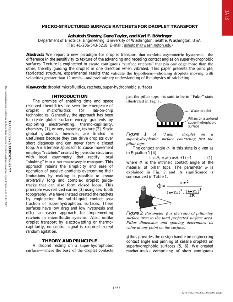
3A1.5 MICRO-STRUCTURED SURFACE RATCHETS FOR DROPLET TRANSPORT Ashutosh Shastry, Dane Taylor, and Karl F. Böhringer Department of Electrical Engineering, University of Washington, Seattle, Washington, USA (Tel: +1-206-543-5218; E-mail: ashutosh@washington.edu) Abstract: We report a new paradigm for droplet transport that exploits asymmetric hysteresis—the difference in the sensitivity to texture of the advancing and receding contact angles on super-hydrophobic surfaces. Texture is engineered to create contiguous “surface ratchets” that pin one edge more than the other, thereby guiding the droplet in one direction when vibrated. This paper presents the principle, fabricated structure, experimental results that validate the hypothesis—showing droplets moving with velocities greater than 12 mm/s—and preliminary understanding of the physics of ratcheting. TRANSDUCERS & EUROSENSORS ’07 The 14th International Conference on Solid-State Sensors, Actuators and Microsystems, Lyon, France, June 10-14, 2007 Keywords: droplet microfluidics, ratchets, super-hydrophobic surfaces INTRODUCTION The promise of enabling time and space resolved chemistries has seen the emergence of droplet microfluidics for lab-on-chip technologies. Generally, the approach has been to create global surface energy gradients by exploiting electrowetting, thermo-capillarity, chemistry [1], or very recently, texture [2]. Static global gradients, however, are limited in usefulness because they can drive droplets over short distances and can never form a closed loop. An alternate approach to cause movement employs “ratchets” created by periodic structures with local asymmetry that rectify local “shaking” into a net macroscopic transport. This approach retains the simplicity and ease of operation of passive gradients overcoming their limitations by making it possible to create arbitrarily long and complex droplet guidetracks that can also form closed loops. This principle was realized earlier [3] using saw-tooth topography. We have instead created the ratchets by engineering the solid-liquid contact area fraction of super-hydrophobic surfaces. These surfaces have low drag and low hysteresis and offer an easier approach for implementing ratchets in microfluidic systems. Also, unlike droplet transport by electrowetting or thermocapillarity, no control signal is required except random agitation. just the pillar tops—is said to be in “Fakir” state illustrated in Fig. 1. Water droplet Pillars on a textured super-hydrophobic surface Figure 1: A “Fakir” droplet on a superhydrophobic surface contacting just the pillar tops. The contact angle șF in this state is given as in Equation 1 [4]. cos șF = I (cosși +1) í1 (1) where și is the intrinsic contact angle of the material of pillar tops. The parameter I is explained in Fig. 2 and its significance is summarized in Table 1. Figure 2: Parameter I is the ratio of pillar-top surface area to the total projected surface area. Pillar dimension and spacing determines its value at any point on the surface. I thus provides the design handle on engineering THEORY AND PRINCIPLE A droplet resting on a super-hydrophobic surface—where the base of the droplet contacts 1353 contact angle and pinning of sessile droplets on superhydrophobic surfaces [5, 6]. We created ratchet-tracks comprising of short contiguous 1-4244-0842-3/07/$20.00©2007 IEEE 3A1.5 contact angle gradients by systematically varying pillar spacing as shown in Fig 3a. Table 1: Summary of the effect of parameter I on the apparent contact angle TF and the degree of pinning of the droplet edges due to hysteresis. Hysteresis/Pinning Parameter Contact Advancing Receding I angle TF Low High Low Low High Low Low High TRANSDUCERS & EUROSENSORS ’07 The 14th International Conference on Solid-State Sensors, Actuators and Microsystems, Lyon, France, June 10-14, 2007 Ratchet-tracks are surrounded by a low I (I=0.04) region that serves to repel the droplets ensuring that they do not stray from the tracks. At equilibrium, edges of the droplet stay in energy valleys shown in Fig 3b. Figure 3: L-Edit layout of pillars. Low density of pillars corresponds to high contact angle and therefore high energy. The saw-tooth energy topography of the ratchet-surface is depicted in the lower plot. Curves of maximum effective I in opposite direction. The droplet edge that curves in the same direction as the pillars encounters higher pillar density per unit length than the other edge even when the two edges are located on identical texture. This is illustrated in Fig. 4. When the droplet is vibrated in the vertical direction, the base of the droplet expands and contracts once in every cycle of vibration. Since advancing angle is insensitive to texture, we expect that the two edges would advance identically [5, 6]. Receding angle is however sensitive to texture, so we expect more pinning of the edge curved in the same direction as pillars when the edges retract. Consequently, in each cycle, the droplet is expected to move in the direction of pinned edge. MATERIALS AND METHODS L-Edit® was used to create mask layouts. Ratchets were realized with identical circular pillars of 20Pm diameter. Their spacing varied from 20Pm to 100Pm to realize different values of I. Curvature of the pillar rows was varied from 0.5mm to 1mm. These layouts were converted to GERBER® format and printed to obtain the transparency masks. Fig. 5 details the fabrication process used to obtain the test dies. Wet oxidation of 4” <100> silicon wafers was carried out at 1100oC to grow 0.3Pm of oxide. Photolithography was done with AZ1512® resist to transfer the mask pattern on the oxide. Oxide was then etched with buffered oxide etch (BOE) to open windows in it. Deep reactive ion etching was performed using standard Bosch® process to obtain the pillars 0.3 Pm oxide grown Figure 4: Front (left) edge of the receding droplet encounters more pillars than the back (right) edge, creating asymmetry. The pillars are laid along a curve. Consider the base of the droplet in two halves. One half has the edge of the base curving in the same direction as pillars and in the other half it curves 1354 Lithography and oxide etch Silicon Thermally grown oxide DRIE to etch 25Pm tall pillars Piranha activation followed by CVD of FOTS AZ 1512 photoresist Fluorinated octyl trichloro silane (FOTS) Figure 5: Fabrication process for the test surfaces. 1-4244-0842-3/07/$20.00©2007 IEEE 3A1.5 shown in Fig. 6. Finally, the surface was activated in piranha and given a hydrophobic coating of fluorinated-octyl-trichloro-silane (FOTS) using chemical vapor deposition [6]. 200 Pm TRANSDUCERS & EUROSENSORS ’07 The 14th International Conference on Solid-State Sensors, Actuators and Microsystems, Lyon, France, June 10-14, 2007 Figure 6: SEM micrograph of fabricated ratchet surfaces in silicon. The circular pillars all have a diameter of 20Pm and the pitch is varied as required by the design of that particular ratchet. Schematic of a typical droplet is overlaid on the micrograph to elucidate the difference in number of pillars encountered by the two edges. The characterization set-up is explained in Fig. 7. The test die was glued to a stage mounted on a speaker diaphragm. The assembly was kept under a microscope fitted with a high speed CCD camera. Droplets of sizes ranging from 5Pl to 15Pl were manually dispensed with a Hamilton® syringe at one end of the ratchettrack. A square wave of 49 Hz and gradually increasing amplitude was applied to the speaker to actuate the droplets. As the droplet ratcheted across the field of view, its silhouette was recorded at 800 frames-per-second. Figure 7: Schematic of the test set up. Silhouette of droplets was recorded for video analysis. RESULTS AND DISCUSSION Fig. 8 shows two droplets moving in opposite directions guided by their respective ratchet-tracks. 1355 Figure 8: Time shots of droplets moving on ratchet-tracks. Die is mounted on a speaker, actuated by a function generator connected through an amplifier. A 49Hz square wave is gradually ramped till both droplets (~10Pl) begin to move. The marginally smaller droplet (left) is set in motion first. As the amplitude of vibration is gradually increased, initially the droplets remain stuck. The edges oscillate but there is no translation of the droplet. When the amplitude reaches a threshold value, the smaller droplet begins to move. The amplitude is increased further to trigger the take off of the second droplet in the opposite direction. Fig. 9 shows the oscillations of the two edges of the droplet as it moves. In each cycle, the edges “advance” outward when the stage moves up and “recede” inward when the stage moves down. The peaks correspond to advancing angles and the troughs to receding angles. The higher amplitude of oscillation of the leading edge—the edge that is curved in the same direction as the pillars—is a direct consequence of the higher pinning that it experiences as it encounters more pillars. A frame-by-frame MATLAB® analysis of the video yields position and velocity of droplet detailed in Fig. 10. As the amplitude of vibration increases, the energy coupled to the droplet increases. In zone 1 seen in Fig. 10, this energy is very small and the edges remain “stuck” to the surface. They do not oscillate as evident from the figure. The footprint of the droplet remains constant. In zone 2, the edges begin to oscillate but the energy supplied to the droplet is 1-4244-0842-3/07/$20.00©2007 IEEE 3A1.5 TRANSDUCERS & EUROSENSORS ’07 The 14th International Conference on Solid-State Sensors, Actuators and Microsystems, Lyon, France, June 10-14, 2007 Figure 9: Peaks correspond to maximum advancing angle and the troughs correspond to the minimum receding angle. The amplitude therefore corresponds to pinning or hysteresis experienced by the edges. Greater pinning of the leading edge is evident from the higher amplitude of oscillation. comparable to that dissipated in movement of the edges. Since the edges begin to oscillate, the droplet begins to translate as well. In zone 3, the energy supplied by vibration is very high, so the droplet begins to jump. However, the time spent when the droplet is off-contact is dead-time. Hence the ratcheting efficiency drops in zone 3. Consequently, the advantage of high amplitudes of oscillation is compensated by reduced ratcheting efficiency and the droplet is observed to move with a terminal velocity that is independent of amplitude. CONCLUSIONS This work demonstrates that microstructure of super-hydrophobic surfaces can be exploited to guide droplets along desired linear or circular trajectories over arbitrarily long distances. Design rules for achieving maximal ratcheting efficiency are being developed. ACKNOWLEDGEMENTS This work is funded by NIH Center of Excellence in Genomic Science and Technology grant 1-P50-HG002360-01. REFERENCES: [1] A. Darhuber and S. M. Troian, Ann. Rev. Fluid. Mech., vol. 37, pp. 425–455, 2005. 1356 . Figure 10: Amplitude of vibration of the stage is gradually increased. Three distinct zones are observed. Zone 1: Energy supplied by vibration is very low so the droplet remains “stuck”. Zone 2: “Slip-stick” behavior is evident because pinning of the leading edge while receding, mainfests as clipping of tops. The droplet accelerates. Zone 3: The droplet moves with a constant velocity of 12.5 mm/s. Increasing energy due to rising amplitude is compensated by decreased ratcheting efficiency. The droplet moves with a “terminal velocity”. [2] A. Shastry, M. J. Case and K. F. Böhringer, Langmuir, vol. 22 (14), pp. 6161 -6167, 2006. [3] O. Sandre, L. Gorre-Talini, A. Ajdari, J. Prost, and P. Silberzan, Phys. Rev. E., 60(3), 2964-2962, 1999. [4] Pierre-Gilles de Gennes, F. Brochard-Wyart, D. Quere. Capillarity and Wetting Phenomena: Drops, Bubbles, Pearls, Waves, Springer-Verlag New York, Inc. 2004. [5] A. Shastry, S. Abbasi, A. Epilepsia and K. F. Böhringer, “Contact Angle Hysteresis Characterization of Textured Superhydrophobic Surfaces”, In Proc. of Transducers, June 2007, Lyon, France. [6] A. Shastry, S. Abbasi and K.F. Böhringer, “Rolling and Sliding Fakir Drops Explain Contact Angle Hysteresis Behavior of Microtextured Superhydrophobic Surfaces”, submitted, 2007. 1-4244-0842-3/07/$20.00©2007 IEEE


