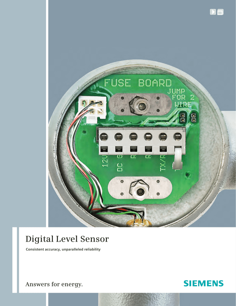
Digital Level Sensor
Consistent accuracy, unparalleled reliability
Answers for energy.
Consistent accuracy
Unparalleled reliability
2
The Siemens Digital Level Sensor
(DLS) is an engineered solution for
remotely monitoring liquid levels
in storage tanks. In addition to
offering true digital level
measurement in precise
increments, it accurately and
repeatedly measures two different
fluid densities and up to eight
temperatures on the same sensor.
Its accuracy is maintained over the
entire life of the sensor, thereby
helping to reduce long-term
maintenance costs.
3
Model 1000 Digital Level Sensor specifications
Standard features, applications,
benefits
Intrinsically safe apparatus
approved to meet UL913 standard
for safety
Low maintenance
Temperature changes do not affect
accuracy, unlike many other level
sensing devices
Applications include production
monitoring, inventory control, leak
detection, remote read-out of level in
H2S environment, high/low alarms and
many other applications
All electronics are sealed inside the
sensor tube
Sensor tube available in stainless
steel and fiberglass
Intrinsically safe apparatus when
connected to RLD model 1010 barrier
board
ETL-approved intrinsically safe barriers
available to mount with the RTU
Field wiring that connects to a surgeprotected fuse board shielding the
sensor electronics from lightning
damage
Proven for use in many different fluids
and environments, including crude oil,
water, diesel, kerosene, condensate
and gasoline
Explosion-proof junction box suitable
for connecting to rigid conduits
Standard ASCII protocol for
communicating with several existing
remote terminal units via RS485/RS232
Digital-to-analog conversion available
for outputting either a 4-20mA or
1-5 VDC analog signal
4
Measurement length
Available from 2’ to 30’ in 1’ increments
Longer sizes available as custom orders
Tubing material
316L stainless steel: standard
18 gauge: standard
14 gauge: optional
Fiberglass: optional
Float
NYTROPHYL stainless steel: standard
Power requirements
12 VDC +/- 15% at sensor terminals
Power consumption
45mA nominal
70mA maximum
Pressure
15 psi: standard
Higher pressure ratings
available as custom orders
Communication
UHMW-NYTROPHYL: optional
RS485
One standard, two optional for water
interface
Two- or four-wire communications
Fits either 3” or 4” tank ports
Level measurement increments
and accuracy
Baud rate and parity programmable
(up to 38400 baud)
4-20mA signal available when
connected to digital-to-analog
converter board
Standard
1/4” resolution (+/- 1/8” accuracy)
1/2” resolution (+/- 1/4” accuracy)
Operating temperature range
-40° F to +185° F: standard
Wiring
Two-wire communication: two twisted
pair, (16-18 AWG) recommended
Four-wire communication: three
twisted pair, (16-18 AWG)
recommended
-40° F to +240° F: optional
Temperature measurement
Display of °F: standard
First sensor 12” from bottom: standard
1-8 temperature sensors available with
desired spacing: optional
+/- .5° F accuracy
5
Model 1000 terminal unit
The Model 1000 terminal unit is a solidstate stand-alone device designed to read
the digital signal from the Model 1000
Digital Level Sensor (DLS) and convert it
to an analog output. The intent is to
enable the superior accuracy of the
Model 1000 DLS to be used in a system
that has only analog inputs available for
receiving tank level data.
This unit can poll up to 16 individual
Model 1000 DLS units and output up to
eight analog signals based upon data
received from the Model 1000 DLS. The
analog outputs are user programmable
for either level or temperature from a
particular sensor. Each analog loop can
be set up to either source power or be
powered by the host unit. This unit is
programmable through a standard RS232
serial cable with RTS/CTS connected to a
computer running the Model 1000
terminal configuration software or any
terminal emulation software. Local
readout for the tank levels and
temperature are available with a four-line
by 20-character LCD display. It will display
up to two levels, temperature and tank
volume for each tank. Sockets are
provided for two optically isolated G4
digital output modules for alarming or
controlling based on user programmable
set points for any sensors.
The G4 modules can control either AC or
DC power to dry contact relays. An
expansion board has been developed to
allow for eight additional optically
isolated G4 digital output modules. With
this expansion board, a total of 10 digital
outputs are available.
Mechanical specifications
NEMA 4X enclosure
Optional eight D/O expansion board
can be mounted inside enclosure
Electrical specifications
Operating temperature range:
-40° C to +85° C
When equipped with LCD display,
operating temperature is 0° C to 70° C
Optional display heater for cold
operating conditions
Power requirements: 12 to 15 VDC
RS232 port
Provided for configuration and
diagnostics
9600 baud, no parity, eight data bits,
one-stop bit
Communication: HyperTerminal or
similar terminal emulation software
using ASCII commands
Configuration software available
RS485 port
Communication to the Model
1000 DLS
Four-wire communications
Power consumption
Standby without display: 75mA*
Standby with display: 85mA*
During scroll - LCD backlight: 210mA*
(scrolling period is programmable)
During poll: 100mA*
(polling time = 2 sec max)
Sleep mode: 9mA**
Analog outputs: 20mA max per
channel if unit sources loop power
*Power consumption does not include connected level
sensors. User must consider each sensor connected will
draw an average 45mA.
**Sleep mode is designed for stand-alone display
applications with no digital or analog outputs
programmed.
Cycles power to level Model
1000 DLS between polls
4-20mA conversion accuracy
(except as limited by sensor and protocol
resolution)
Resolution: 16 bit
Monotonicity: 16 bit min
Integral non-linearity: +/- 0.01% of FS
max offset (4mA) at 25°C +/- 0.1% of
FS max
Offset drift: +/- 25 ppm of FS/°C max
Total output error: (20mA) at
25°C +/- 0.2% of FS max
Total output drift:
+/- 50 ppm of FS/°C max
VCC supply sensitivity:
50 mA/mV typical
Optional digital outputs
Total of 10 output sockets available
Model 1000 four-channel
output board
DAC4
The DAC4 is a solid-state stand-alone
interface board that polls the Model 1000
DLS and outputs a 4-20mA analog signal
for use by other field data collection
equipment. The intent is to enable the
superior accuracy of the Model 1000 DLS
to be used in a system that has only
analog inputs. The interface board can
poll up to four Model 1000 DLS and
output up to four analog signals based
upon data received from these sensors.
Not all analog channels need to be used.
The analog signal can output the level or
temperature data from a particular
sensor.
Electrical specifications
Operating temperature range:
-40° C to +85° C
Power requirements: 12 to 15 VDC
Power consumption
Standby: 38mA
During poll: 145mA*
(polling time = 2 sec max)
Analog outputs: 20mA max per channel
if unit sources loop power
*Power consumption does not include connected level
sensors. User must consider each sensor connected will
draw an average 45mA.
RS232 port
RS485 port
Communication to the Model
1000 DLS
Two- or four-wire communications
Cycles power to Model 1000 DLS
between polls
4-20mA conversion accuracy
(except as limited by sensor
and protocol resolution)
Resolution: 16 bit
Monotonicity: 16 bit min
Integral non-linerarity:
+/- 0.01% of FS max
Offset (4mA) at 25° C:
+/- 0.01% of FS max
Offset drift: +/- 0.25 ppm/°C
Total output error: +/- 0.2% of FS max
Total output drift: +/- 50 ppm/°C VCC
supply sensitivity: 50 mA/mV
For any specifications not listed above,
please see the specifications listed under
the Model 1000 terminal unit.
Model 3005 analog
board
The Model 3005 is designed to provide
a single analog output from the Model
1000 DLS. It provides a 4-20mA signal
output for the total fluid level of the tank.
This is an alternative to the Model 1000
terminal unit. It is intended for locations
requiring an analog signal for the tank
level where only one or two tanks are on
location. The Model 3005 replaces the
fuse board in the explosion-proof
housing on top of the Model 1000 DLS.
It provides the same protection to the
Model 1000 DLS as the fuse board
provides. The Model 3005 requires
24 VDC and controls power to the level
sensor. It powers the sensor on a preprogrammed schedule, polls for the level
analog value, powers the sensor down
and outputs the analog signal. The
configurations for the Model 3005 are
stored in the EEPROM of the Model
1000 DLS, allowing for replacement
when required.
Electrical specifications
Operating temperature range:
-40° C to +85° C
Power requirements: 24 VDC +/- 10%
Requires 125mA max
Requires two wires for power and two
wires for 4-20mA loop 4-20mA
conversion accuracy (except as limited
by sensor and protocol resolution)
Provided for configuration and
diagnostics
Resolution: 16 bit
9600 or 1200 baud communicates
using HyperTerminal or similar
terminal emulation software using
ASCII commands
Integral non-linearity: +/- 0.012% max
Monotonicity: 16 bit min
Offset: +/- 0.05% max
Total output error: +/- 0.15% max
Two sockets provide for optically
isolated G4 modules on board
(G4 modules sold separately)
6
Eight additional sockets with
expansion board
7
Published by and copyright © 2009:
Siemens AG
Energy Sector
Freyeslebenstrasse 1
91058 Erlangen, Germany
Siemens Energy, Inc.
Oil and Gas Division
10730 Telge Road
Houston, TX 77095
1 (888) 856-4528 or +1 (281) 856-4530
Order No. E50001-D440-A123-V1-76US
Printed in USA
TD 20091118133638518T BR 1109.25
All rights reserved.
Trademarks mentioned in this document
are the property of Siemens AG, its affiliates,
or their respective owners.
Subject to change without prior notice.
The information in this document contains
general descriptions of the technical options
available, which may not apply in all cases.
The required technical options should therefore
be specified in the contract.
www.siemens.com/energy


