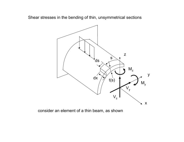
Shear stresses in the bending of thin, unsymmetrical sections z s ds
advertisement

Shear stresses in the bending of thin, unsymmetrical sections ds z s Mz dx y t(s) My Vy Vz x consider an element of a thin beam, as shown σ xx q =τt q + dq ds dx dA ∑F x dσ xx σ xx + dx dx =0 dσ xx ⎞ ⎛ dx ⎟ dA − σ xx dA = 0 ( q + dq ) dx − qdx + ⎜ σ xx + dx ⎝ ⎠ dσ dq = − xx dA dx If we integrate from s1 to s2 s1 s2 q ( s1 ) q ( s2 ) A s2 dσ xx dA dx A ∫ dq = −∫ s1 dσ xx dA dx A q ( s2 ) − q ( s1 ) = Δq = − ∫ Since σ xx M ( = I + M z I yz ) z − ( M z I yy + M y I yz ) y y zz Vz (I 2 − I I yy zz yz ) −Vy −Vy Vz dM y ⎛ dM y ⎞ ⎛ dM z ⎞ dM z I zz + I yz ⎟ z − ⎜ I yy + I yz ⎟ y ⎜ dx dx dx dσ xx ⎝ dx ⎠ ⎝ ⎠ = dx ( I yy I zz − I yz2 ) dσ xx (Vz I zz − Vy I yz ) z − (Vz I yz − Vy I yy ) y = 2 dx I I I − ( yy zz yz ) placing this in our shear flow expression gives VI ( Δq = z yz where − Vy I yy ) Qz + (Vy I yz − Vz I zz ) Qy D D = I yy I zz − I yz2 Qz = ∫ ydA A Qy = ∫ zdA A If we have a symmetrical expression and if Vy = 0 Δq = −Vz Qy I yy If q(s1) =0 then Δq = τ ( s1 ) t ( s1 ) τ= and we obtain −Vz Qy I yy t the minus sign is here since we have taken + Vz Note: in our expression for Δq the q flows "out" from the end of the section under consideration, whether the section is cut from the left or right of the cross section. At the beginning of the section the q flows "in". Examples: q ( s1 ) s1 q ( s1 ) s1 A A q ( 0) in both these cases Δq = q ( s1 ) − q ( 0 ) q ( 0) VI ( = z yz − Vy I yy ) Qz + (Vy I yz − Vz I zz ) Qy D Just as in the torsion of closed sections, the shear flows generated by bending must be conserved at a junction. This follows from equilibrium: dx q3 σ xx q1 q2 ∑F x dσ xx dx σ xx + dx dA =0 dσ xx ⎞ ⎛ σ q + q + q dx + + dx ⎟ dA − σ xx dA = 0 ( 1 2 3 ) ⎜ xx dx ⎝ ⎠ dA ( q1 + q2 + q3 ) + dσ xx = 0 dx so as dA → 0 q1 + q2 + q3 = 0 i.e. the net shear flow out of (or into) a junction must be zero A 1000 lb load produces bending but no twisting in the thin open section shown below. Determine the shear flow distributions in this section and the location of the shear center. Assume the thickness of all sections is 0.1 in. All dimensions are measured to the mid planes of the walls. 3 5 z 1000 lb y e S 3 5 all dimensions are in inches 10 3 5 y1 A yc = B A1 C z = yc A3 10 2 × ( y1 A1 ) + ( 0 ) A3 2 A1 + A3 ( 2 )(8)( 0.1)(1) ( 2 )( 8)( 0.1) + (10 )(.1) = 0.6154 in y A2 E F D so we have y2 3 Vz = 1000 lb, Vy = 0, I yz = 0 Δq = 5 −Vz Qy I yy negligible 1 3 2⎤ 3 ⎡1 I yy = 2 × ⎢ ( 8 )( 0.1) + ( 8 )( 0.1)( 5 ) ⎥ + ( 0.1)(10 ) ⎣12 ⎦ 12 = 48.33 in 4 Δq = for AB s1 q=0 −1000 Qy = −20.69Qy 48.33 q ( s1 ) z 5 y Δq = q ( s1 ) − 0 = −20.69 ⎡⎣( 0.1)( s1 )( 5 ) ⎤⎦ q ( s1 ) = −10.35 s1 lb / in q1B = −31.03 lb / in A 3 B for BC z q ( s2 ) s2 q=0 5 y Δq = q ( s2 ) − 0 = −20.69 ⎡⎣( 0.1)( s2 )( 5 ) ⎤⎦ q ( s2 ) = −10.35 s2 qB2 = −51.75 lb / in B 5 C qB3 for BD s3 z 5 q ( s3 ) y Δq = q ( s3 ) − qB3 = −20.69 ⎡⎣( 0.1)( s3 )( 5 − s3 / 2 ) ⎤⎦ q ( s3 ) = qB3 − 10.35 s3 + 1.035 s32 31.03 51.75 qB3 qB3 + 51.75 − 31.03 = 0 qB3 = −82.78 lb / in q ( s3 ) = −82.78 − 10.35 s3 + 1.035 s32 At the middle q ( 5 ) = −109 lb / in -82.78 q ( s3 ) = −82.78 − 10.35 s3 + 1.035 s32 -109 -82.78 For the lower flange Qy is the same as for the upper flange but with opposite sign so we have +31.03 E 3 D +51.75 D 5 F the total forces carried by each section: R2 R1 the entire shear stress distribution: 10 3 5 3 R1 = ∫ 10.35s1ds1 = 46.58 lb 0 5 R2 = ∫ 10.35s2 ds2 = 129.38 lb 0 10 10 R3 R1 R2 3 5 Note: we have used the negative of the shear flow expressions to agree with the directions assumed for the forces shown R3 = ∫ ( 82.78 + 10.35s3 − 1.035s32 ) ds3 = 1000 lb 0 to find the shear center R2 R1 1000 lb e 3 R3 10 O 10 O 5 R1 R2 3 5 We obtained the shear flow distributions under the assumption that there was only bending. These shear flows will generate the shear forces and their moments about a particular point (i.e. the force locations). Thus, we can determine the shear center here by requiring that the moment of the 1000 lb load about any point produce the same moments as the shear flows, ∑M O = 1000 e ∑M 1000e = 828 e = 0.828 in O = 10 R2 − 10 R1 = (129.38 − 46.58 )(10 ) = 828 in − lb location of the shear center by sectorial area s2 C B A s1 S e O 5 5 D E F s3 BD ω = ω0 + es1 AC ω = ω0 + 5e + 5s2 EF ω = ω0 − 5e + 5s3 take the starting point for the integration at O ∫ ω dA = 0 3 5 ⎡5 ⎤ t ⎢ ∫ (ω0 + es1 ) ds1 + ∫ (ω0 + 5e + 5s2 ) ds2 + ∫ (ω0 − 5e + 5s3 ) ds3 ⎥ = 0 −5 −3 ⎣ −5 ⎦ odd 10ω0 + 8ω0 + 8ω0 = 0 ω0 = 0 so the sectorial area distribution looks like: + Thus, + z s1 ∫ yω dA = 0 automatically and we need only consider ∫ zω dA = 0 - ∫ zω dA = 0 3 5 ⎡ +5 ⎤ t ⎢ ∫ ( es1 ) s1ds1 + 5 ∫ ( 5e + 5s2 ) ds2 + ( −5 ) ∫ ( −5e + 5s3 ) ds3 ⎥ = 0 −5 −3 ⎣ −5 ⎦ z = s1 z = 5 which gives z = −5 250 e + 400e − 400 = 0 3 e= 400 = 0.828 in 400 + 250 / 3


