S206E057 – Spring 2016
S206E057 -- Lecture 15, 5/22/2016, Rhino 3D, Grasshopper, Shanghai Tower modeling
Copyright ©2016, Chiu-Shui Chan. All Rights Reserved.
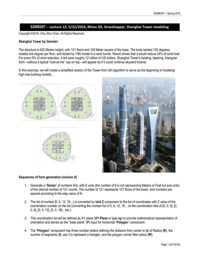
Shanghai Tower by Gensler:
The structure is 632 Meters height, with 121 floors and 120 Meter square of the base. The body twisted 120 degrees,
rotated one degree per floor, and tested by 1/85 model in a wind tunnel. Result shows that it would reduce 24% of wind load.
For every 5% of wind reduction, it will save roughly 12 million of US dollars. Shanghai Tower’s twisting, tapering, triangular
form—without a typical “look-at-me” cap on top—will appear as if it could continue skyward forever.
In this exercise, we will create a simplified version of the Tower from GH algorithm to serve as the beginning of modeling
high-rise building models..
Sequences of form generation (version A)
1. Generate a “Series” of numbers first, with 6 units (the number of 6 is not representing Meters or Feet but just units)
of the interval number of 121 counts. The number of 121 represents 121 floors of the tower, and numbers are
spaced according to the step value of N.
2. The list of number [0, 6, 12, 18…] is converted by Unit Z component to the list of coordinates with Z value of the
coordination number on the list (converting the number list of 0, 6, 12, 18… to the coordination lists of [0, 0, 0], [0,
0, 6], [0, 0, 12], [0, 0, 18]…etc.).
3. This coordination list will be defined as XY plane (XY Plane or type xy) to provide mathematical representation of
orientation and serves as the “base plane” (P) input for horizontal “Polygon” component.
4. The “Polygon” component has three number sliders defining the distance from center to tip of Radius (R), the
number of segments (S, use 3 to represent a triangle), and the polygon corner fillet radius (Rf).
Page 1 (5/1/2016)
Arch534 – Spring 2015
5. The polygon output of (P) represents the floor. There are 121 polygons created and each will be rotated. The
rotation starts from 0 to 0.75. Here, each plane’s rotation angle is controlled by “Construct Domain” component to
build up a domain ranged from 0 to 0.75 and distributed 121 times. The range component will take the list from
Domain output as its input to generate a list of 121 numbers evenly spread out (or cut) from 0 to 0.75.
For instance, the interval between two numbers is obtained by 0.75 / 121 = 0.006198, and 0.006198 * 121 is
0.749958. In GH, the unit of angle always is treated as radian (1 degree = 0.0174533 radian). Here, each number is
multiplied (Multiplication) by PI to get the number of 0, 0.019, 0.038, 0.058…for 0, 0.006198, 0.012397,
0.018595…etc., to simulate a close value for rotation. Accordingly; each plane will be rotated along the number
given by this AxB component. If we divide the R from AxB component by 180 to get a real representation of radian
unit, we will get a very small rotation angle. So, it is not done so. This explains the notion of representation in data
input.
6. The rotated plane will also be scaled from bottom floor to the top floor with non-uniform factor (ScaleNU)
component. In ScaleNU, G is the geometry obtained from “Rotate”. The X and Y axis of each plane will be scaled
by a “Series” of numbers; the number will gradually be reduced by the interval of -0.005, 121 times. In this
example, we don’t want the original shape on the ground to be scaled by -0.005, so the starting number of the
series is forced to be “1” instead of the default value of 0. The negative number determines the reducing factor that
versus the positive number to increase the size (width) of the polygon.
7. Finally, the rotated triangles are lofted (Loft) to create the tower skin, which will be baked to Rhino as Rhino model.
8. We could put a cap (Cap) to close the top of the tower.
Page 2 (5/1/2016)
S206E057 – Spring 2016
Second version B – the real simulation
1. In GH, the rotation angle is required to show in radians instead of degrees. The conversion is done by the method
of getting the number in Range output times Pi and divided by 180, which is the formula of turning a degree to
radians. See the formula below. In this coding example, we had not divided it by 180 yet. You should modify it to
get exact results.
𝑅𝑅𝑅𝑅𝑅𝑅𝑅𝑅𝑅𝑅𝑅𝑅𝑅𝑅 =
𝐷𝐷𝐷𝐷𝐷𝐷𝐷𝐷𝐷𝐷𝐷𝐷𝐷𝐷 ∗ 𝜋𝜋
180
𝐷𝐷𝐷𝐷𝐷𝐷𝐷𝐷𝐷𝐷𝐷𝐷𝐷𝐷 =
𝑅𝑅𝑅𝑅𝑅𝑅𝑅𝑅𝑅𝑅𝑅𝑅𝑅𝑅 ∗ 180
𝜋𝜋
Changing the degrees to radians is done by the following formula.
2. There is a method of using Radian directly to convert degree to radian quickly, which is the focus on this version.
Similarly, we could also use the function of “Degrees” to turn radian to degrees.
In this case, the Range component creates a list of 122 items of numbers (0 and 121 represent the ground and
roof levels respectively), which is arranged by the value coming from Domain component to make appropriate list.
As a result, it will have 122 items of consecutive number representing one degree of rotation angle for each floor
and which are converted into radian for rotation input.
3. In this version B example, each floor will rotate one degree from the first floor to the 121th floor. So, this is a real
simulation of the building rotation. The resulting image and codes are shown below.
Page 3 (5/1/2016)
Arch534 – Spring 2015
Version C:
In this version C, we could pre-define the maximum number of rotation as 121 degrees (or 90, 180 degrees etc.) for all 121
floors. So, the program calculates the radians unit by π / 180 (Division), which is 0.0147453, and multiplies it by the
number of 121 to determine the “Domain” of rotation range (0 to 2.111848). The value of 2.111848 is the total rotation angle
in radian. Thus, the “Range” component sets up the boundary ranging from 0 to 2.111848. In other words, the Range
component will calculate 121 units of rotation angles individually.
The coding is attached here for reference. The resulting image is provided below next to the real photo for comparison.
Final exercise requirements:
1. Apply the second version to modify and change the rotation orientation to clock wise direction, see the images
below.
2. Again, apply the second version to make the base size wider to match the real base size of around 120 Meter
square units of distance with the height around 3.3 meters.
3. Make the tower as a circular shape instead of a triangular shape. You have to find out the most efficient way
(number) to create it?
4. Bake the “Loft” component and save it to a particular layer. Render the image and save the Rhino image to JPG
file. Please load both image and GH file to my.files server for completing today’s exercise.
Page 4 (5/1/2016)
S206E057 – Spring 2016
Version 4: Construct the floor plane and the envelop.
1. Use Boundary Surface to make surfaces from the un-uniformed scale list, which represents each floor and
extrude each along Z axis with 1 foot distance to create the floor plane.
2. From the Loft (or Cap) output, apply Extrude to extrude the surface along X axis to create exterior walls.
Happy Spring Break!!!
Page 5 (5/1/2016)

