S206E057 – Spring 2016
S206E057 -- Lecture 9, 5/20/2016, Rhino Advanced Features 2 – an overview
Copyright ©2016, Chiu-Shui Chan. All Rights Reserved.
Blend Surface Feature:
Rhino has a number of tools to match up two separate surfaces.
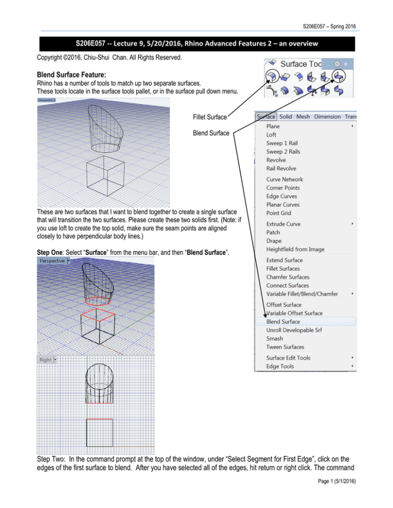
These tools locate in the surface tools pallet, or in the surface pull down menu.
Fillet Surface
Blend Surface
These are two surfaces that I want to blend together to create a single surface
that will transition the two surfaces. Please create these two solids first. (Note: if
you use loft to create the top solid, make sure the seam points are aligned
closely to have perpendicular body lines.)
Step One: Select “Surface” from the menu bar, and then “Blend Surface”.
Step Two: In the command prompt at the top of the window, under “Select Segment for First Edge”, click on the
edges of the first surface to blend. After you have selected all of the edges, hit return or right click. The command
Page 1 (5/1/2016)
Arch534 – Spring 2015
prompt will now say “Select Segment for Second Edge”. Select the second set of edges, and hit return or right
click.
Step Three: At the command prompt “Select Seam Point to Adjust. Press Enter When Done” you will get some
additional options. You will also notice that you will get two arrows. These arrows allow you to adjust the location
of the seam to the blended surface and adjust the direction of the surface.
Two Arrows
Seam of Blended Surface Adjusted.
Also in this command prompt you will notice three options “Flip Direction, Automatic, and Natural”. The flip
direction option allows you to orient the arrows in the same direction to avoid a twisted surface. Automatic will
generate the surface automatically. Natural will give a more relaxed look to the surface. Click Enter to Continue.
A preview button will appear where you can adjust the settings.
Generated Surface with Surface > Planar Curves & Rebuild
Page 2 (5/1/2016)
S206E057 – Spring 2016
Flow along Surface and Curve
In Rhino, you can take a set of complex surfaces and flow and distort those
surfaces over another surface. Choose Transform>Flow along Surface.
Surface to Flow Along
Base Surface
Surfaces to Flow
In this example, I use import
to put the bird Rhino model to
the current scene.
At the prompt: Select objects to flow along surface, select the whole bird and hit Return.
At the prompt: Base Surface - select near a corner, Select the base surface, near a corner to be aligned with the flowed
surface.
At the prompt: Target Surface - select near matching corner, click on a corner to align the objects on the surface.
The object is flowed along the surface
The object is flowed along the surface
Resulting Object
Resulting Object
Note: Flow along Curve works in a similar way.
Note the orientation will remain the same way.
Tips: The position of the object on the surface
will be used as the position alignment reference.
If the orientation is not aligned correctly, then
use ‘dir’ and swap U or V to modify the U, V
orientation for getting a better result.
The rigid of “yes” option will not make a smooth
flow.
Page 3 (5/1/2016)
Arch534 – Spring 2015
The Splop Tool:
The Splop Tool is a new type of tool for placing complex objects onto a free flowing surface. It copes, rotates, scales, and
wraps objects on a surface, like pottery springing or applique.
Objects to Splop
Surface to Splop onto
In the command prompt, type in “splop”. At the prompt: Select objects to splop, select the object (bird) to be placed on the
surface.
• At the prompt: Click the center of the object (bird) to define the center of reference sphere, and drag a sphere
around the object to splop.
• At the prompt: Select Surface to splop on: click on the surface.
• A cursor appears and you can place the object, scale it, and rotate it on the surface. Also note that the object
bends and flows over the surface.
Multiple objects placed on a surface.
Page 4 (5/1/2016)
S206E057 – Spring 2016
Using Blocks in Rhino:
Often you will use the same part (object) created in Rhino many
times. If this is the case it is best to use blocks, which is similar to the
Block used in ACAD. Blocks have two major advantages:
1. It keeps the files sizes small and thus you can create
complex models without having large files sizes.
2. If you need to update the part, all the instances of that part
will be updated.
Complex Form that will be turned into a block.
Select Edit>Blocks>Create Block Definition.
At the prompt, select objects to define block, click on
objects and hit Enter.
At the Prompt, define base point, click to set an
insertion point for the block. These procedures are the
same as in ACAD block definition.
The following window will appear:
The block Definition properties will appear.
Give the block a Name and hit OK.
In this example, the block can be used as a pattern that could be repeated many times to create a composition.
Page 5 (5/1/2016)
Arch534 – Spring 2015
Inserting a Block Definition:
After you create a block, you can then insert instances of the block into
the Rhino model. An instance is a reference of an original. This is how
you can keep the file sizes down.
Choose the Block to insert
Select various insertion settings
Click OK to insert
The block will be bound to the mouse and
when clicked, will be inserted
Page 6 (5/1/2016)
S206E057 – Spring 2016
Block Manager: Block Manager is the one that manages all the blocks in the model environment.
Linking External Models as Blocks:
Another powerful way to use blocks is to link a series of
external models into a “Master” Rhino Model. This allows
updates in different models to be automatically updated in the
master model.
Step One: Create a Block from an external file.
Select Edit>Blocks>Insert Block Instance
Select File
Select a Rhino Model to insert
Page 7 (5/1/2016)
Arch534 – Spring 2015
Linked File Name and Pathway is displayed (NOTE: It is a good idea to keep all files in the same folder to avoid
broken links)
Under External File, Choose Link Click OK to place in model
Linked Models
If changes are made in the original model the changes
will appear in the model with the block definitions.
Change Made to the Original Model File
To update the Link Model, click on Edit>Blocks>Block Manager
Page 8 (5/1/2016)
S206E057 – Spring 2016
Select the Block to Update, and click on Update.
Blocks are updated. This
notion is the same as the
block definition used in ACAD.
Page 9 (5/1/2016)
Arch534 – Spring 2015
Make A 2D Drawing:
In Rhino you can generate a series of 2D Drawings from 3D forms these
drawings are a series of 2D curves that can be imported into illustrator or
flash. Note: the size of the objects shown in the viewport determines the
drawing output size.
To make a 2D drawings, click on Dimensions>Make 2-D Drawing.
At the prompt, Select objects to draw > select the objects.
The following Window will appear:
Choose 4 View USA
Click OK
Page 10 (5/1/2016)
S206E057 – Spring 2016
Four Views, Front, Left, Top, and Perspective are created.
These views are located on the ground plane. If you select a view and export it from the top view it will be
oriented in the correct direction.
Rhino and BIM:
RhinoBIM_Structure is a new (including 32 bit and 64 bit) beta version issued in 2015, which is available in the
Manage tab that allows users to attach any information to any geometry and create a documentation report. The
system will be installed in the Program Files / RhinoBIM folder by default.
Summary of module one (exercise of Rhino modeling):
In summary, Rhino shares some similarity with ACAD in terms of key board input, interface arrangement, and a
number of 2D and 3D modeling functions. But, it has limitations and advantages that compare with other major
solid modeling systems. Here are the summaries.
ACAD:
1. ACAD is a very good 2D drafting tool. Especially, it generates very precise drawings for constructional
document.
Page 11 (5/1/2016)
Arch534 – Spring 2015
2. The changes of shapes or forms are very easy to make. It also provides a very good user interface.
3. Thus, ACAD is excellent for drawing and drafting purposes.
Revit:
1. Revit could build up architectural models that include architectural, structural, plumbing, electronic
elements in one file, which could create models and 2D drawings. Thus, it is very good for AEC
constructional document developments.
2. The mental ray rendering effects are awesome.
3. Changes of forms are also easy to be done.
4. Revit is the architectural design field’s industrial standard. Every design firm uses Revit now.
3D MAX
1. It is good for presentation and representation purposes. Particularly, it has the powerful functions of
lighting, rendering, and animation.
2. Its modification panel, that keeps the history of form generation, is an attractive character of the system.
That is why it is called parametric modeling system.
3. Because of the rendering power, most of architectural firms export Revit model to 3D MAX for advanced
and professional rendering.
Rhino
1. Rhino provides a lot of functions to work on curves, NURBs, and polygons meshes, which are good for
generating organic forms. Thus, the system is used mainly for form creation. But, the modification or
revision of generated objects could not be modified easily, which is not that convenient. It is because of
the system has no data history kept for form modification. But, it has the “Undomultiple” function that
allows users to go back to regenerate forms. However, the undo-list will not be available nor kept after
the model file is saved and closed.
2. The rendering function and material definition in Rhino are not sophisticated enough, and they are not
fully covered in this course.
3. The plug-in of Grasshopper provides opportunities of other kind of parametric modeling, which is the
concentration of the next module.
You could explore individual systems more on your own.
Assignment one:
The tutorial sessions explained a lot of major Rhino modeling functions, which should provide a very good foundation for
your modeling assignment. The assignment one, which is due 2/16, will be an exercise on constructing a Rhino model for a
form, a simple architectural building, or complex buildings. The modeling methods are basically the same.
You could use techniques covered so far to create a digital model of your selected objects/building elements. The grade will
be depended upon the level of details and the completeness that your model had accomplished. Yet, the simpler geometry
of the model with high level of details would be better. It is because that complicated surfaces and solids will be difficult to
modify (and edit). Thus, you have to do a lot of experiments with trail-and-error to develop a good digital model for this
assignment.
You could figure out methods of defining good materials for beautiful rendering. But, the concentration of this exercise is to
create a good model, which will be further applied in the next module for Grasshopper exercise. Don’t forget, a building with
a site context is required.
Happy modeling…
Page 12 (5/1/2016)


