Dial Calipers
advertisement
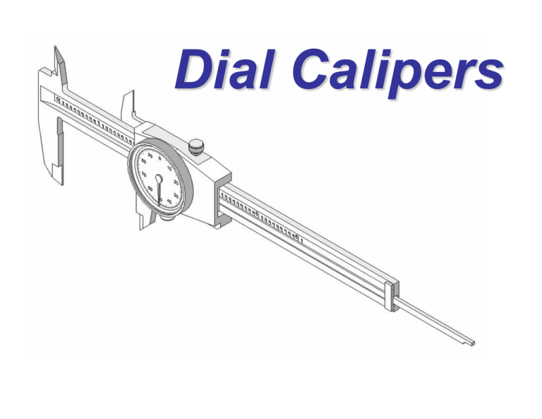
Dial Calipers Dial Calipers General Information Dial Calipers are arguably the most common and versatile of all the precision measuring tools used by engineers and manufacturers. Dial Calipers Four Types of Measurements Dial calipers are used to perform four common measurements on parts… 1. Outside Diameter or Object Thickness 2. Inside Diameter or Space Width 3. Step Distance 4. Hole Depth Outside Measuring Faces These are the faces between which outside length or diameter is measured. Example: Outside Diameter of object Inside Measuring Faces These are the faces between which inside diameter or space width (i.e., slot width) is measured. Example: Inside measuring Step Measuring Faces These are the faces between which stepped parallel surface distance can be measured. Example: Step Distance Depth Measuring Faces These are the faces between which the depth of a hole can be measured. Example: Depth Measuring Note: Work piece is shown in section. Dial Caliper shortened for graphic purposes. Dial Calipers Nomenclature A standard inch dial caliper will measure slightly more than 6 inches. The blade scale shows each inch divided into 10 increments. Each increment equals one hundred thousandths (0.100”). Slider Blade The blade is the immovable portion of the dial caliper. The slider moves along the blade and is used to adjust the distance between the measuring surfaces. Pointer The pointer rotates within the dial as the slider moves backand-forth along the blade. Reference Edge The reference edge keeps track of the larger increments (i.e. 0.100”) as the slider moves along the rack. Rack The gear-toothed rack is used to change linear motion (slider) to rotary motion (pointer). Dial Calipers Reading the Inch Dial Caliper The dial is divided 100 times, with each graduation equaling one thousandth of an inch (0.001”). Every time the pointer completes one rotation, the reference edge on the slider will have moved the distance of one blade scale increment (0.100”). To determine the outside diameter of this pipe section, the user must first identify how many inches are being shown on the blade scale. 1.000” 0.400” The reference edge is located between the 1 and 2 inch marks. So, the user makes a mental note…1 inch. The user then identifies how many 0.1” increment marks are showing to the right of the last inch mark. In this case, there are 4…or 0.400”. 1.000” 0.400” + 0.037” 1.437” Next, the user looks at the pointer on the dial to see how many thousandths it is pointing to. In this case, it is pointing to 37…or 0.037”. The user then adds the three values together… How wide is the block? 1.000” 0.400” + 0.002” 1.402” Practice Time

