Measurement of the position of rotor blade vortices
advertisement

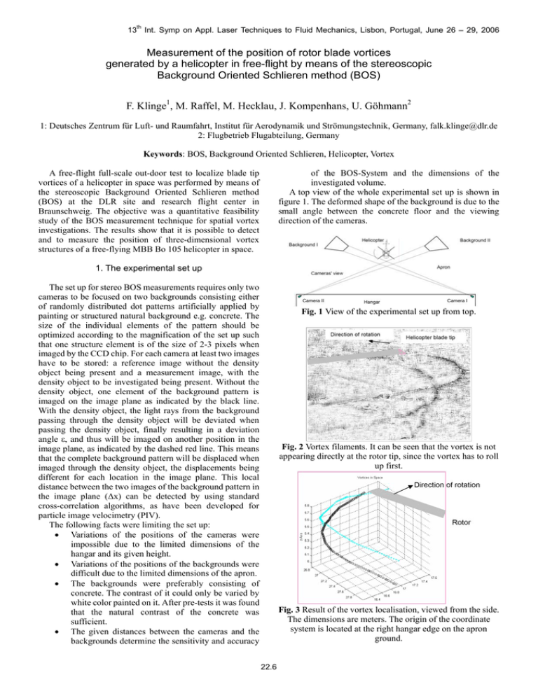
13th Int. Symp on Appl. Laser Techniques to Fluid Mechanics, Lisbon, Portugal, June 26 – 29, 2006 Measurement of the position of rotor blade vortices generated by a helicopter in free-flight by means of the stereoscopic Background Oriented Schlieren method (BOS) F. Klinge1, M. Raffel, M. Hecklau, J. Kompenhans, U. Göhmann2 1: Deutsches Zentrum für Luft- und Raumfahrt, Institut für Aerodynamik und Strömungstechnik, Germany, falk.klinge@dlr.de 2: Flugbetrieb Flugabteilung, Germany Keywords: BOS, Background Oriented Schlieren, Helicopter, Vortex of the BOS-System and the dimensions of the investigated volume. A top view of the whole experimental set up is shown in figure 1. The deformed shape of the background is due to the small angle between the concrete floor and the viewing direction of the cameras. A free-flight full-scale out-door test to localize blade tip vortices of a helicopter in space was performed by means of the stereoscopic Background Oriented Schlieren method (BOS) at the DLR site and research flight center in Braunschweig. The objective was a quantitative feasibility study of the BOS measurement technique for spatial vortex investigations. The results show that it is possible to detect and to measure the position of three-dimensional vortex structures of a free-flying MBB Bo 105 helicopter in space. 1. The experimental set up The set up for stereo BOS measurements requires only two cameras to be focused on two backgrounds consisting either of randomly distributed dot patterns artificially applied by painting or structured natural background e.g. concrete. The size of the individual elements of the pattern should be optimized according to the magnification of the set up such that one structure element is of the size of 2-3 pixels when imaged by the CCD chip. For each camera at least two images have to be stored: a reference image without the density object being present and a measurement image, with the density object to be investigated being present. Without the density object, one element of the background pattern is imaged on the image plane as indicated by the black line. With the density object, the light rays from the background passing through the density object will be deviated when passing the density object, finally resulting in a deviation angle ε, and thus will be imaged on another position in the image plane, as indicated by the dashed red line. This means that the complete background pattern will be displaced when imaged through the density object, the displacements being different for each location in the image plane. This local distance between the two images of the background pattern in the image plane (Δx) can be detected by using standard cross-correlation algorithms, as have been developed for particle image velocimetry (PIV). The following facts were limiting the set up: • Variations of the positions of the cameras were impossible due to the limited dimensions of the hangar and its given height. • Variations of the positions of the backgrounds were difficult due to the limited dimensions of the apron. • The backgrounds were preferably consisting of concrete. The contrast of it could only be varied by white color painted on it. After pre-tests it was found that the natural contrast of the concrete was sufficient. • The given distances between the cameras and the backgrounds determine the sensitivity and accuracy Fig. 1 View of the experimental set up from top. Fig. 2 Vortex filaments. It can be seen that the vortex is not appearing directly at the rotor tip, since the vortex has to roll up first. Fig. 3 Result of the vortex localisation, viewed from the side. The dimensions are meters. The origin of the coordinate system is located at the right hangar edge on the apron ground. 22.6


