Avocent® LongViewTM 4000 Series
High Performance KVM Extender System
Quick Installation Guide
HELPFUL RESOURCES
Product documentation downloads are
available at:
www.avocent.com/manuals
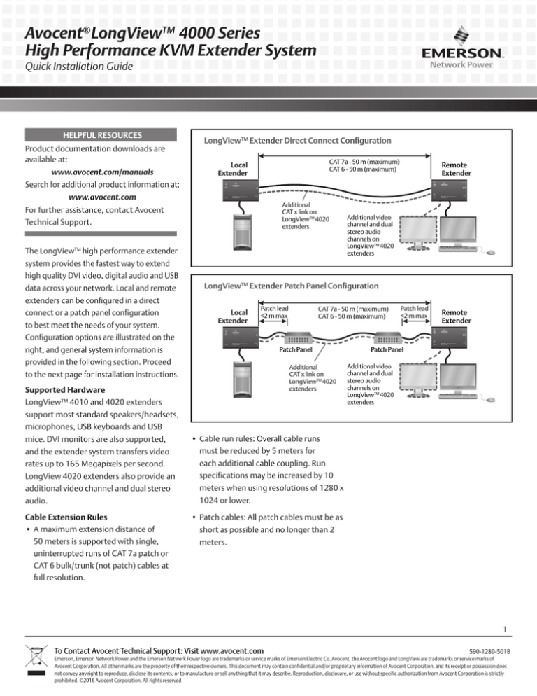
LongViewTM Extender Direct Connect Configuration
CAT 7a - 50 m (maximum)
CAT 6 - 50 m (maximum)
Local
Extender
Remote
Extender
Search for additional product information at:
www.avocent.com
Additional
CAT x link on
LongViewTM 4020
extenders
For further assistance, contact Avocent
Technical Support.
The LongViewTM high performance extender
Additional video
channel and dual
stereo audio
channels on
LongViewTM 4020
extenders
system provides the fastest way to extend
high quality DVI video, digital audio and USB
data across your network. Local and remote
LongViewTM Extender Patch Panel Configuration
extenders can be configured in a direct
connect or a patch panel configuration
to best meet the needs of your system.
Local
Extender
Patch lead
<2 m max
CAT 7a - 50 m (maximum)
CAT 6 - 50 m (maximum)
Patch lead
<2 m max
Remote
Extender
Configuration options are illustrated on the
right, and general system information is
Patch Panel
provided in the following section. Proceed
Additional
CAT x link on
LongViewTM 4020
extenders
to the next page for installation instructions.
Supported Hardware
LongView™ 4010 and 4020 extenders
Patch Panel
Additional video
channel and dual
stereo audio
channels on
LongViewTM 4020
extenders
support most standard speakers/headsets,
microphones, USB keyboards and USB
mice. DVI monitors are also supported,
•Cable run rules: Overall cable runs
and the extender system transfers video
must be reduced by 5 meters for
rates up to 165 Megapixels per second.
each additional cable coupling. Run
LongView 4020 extenders also provide an
specifications may be increased by 10
additional video channel and dual stereo
meters when using resolutions of 1280 x
audio.
1024 or lower.
Cable Extension Rules
•A maximum extension distance of
50 meters is supported with single,
uninterrupted runs of CAT 7a patch or
CAT 6 bulk/trunk (not patch) cables at
full resolution.
•Patch cables: All patch cables must be as
short as possible and no longer than 2
meters.
1
To Contact Avocent Technical Support: Visit www.avocent.com 590-1280-501B
Emerson, Emerson Network Power and the Emerson Network Power logo are trademarks or service marks of Emerson Electric Co. Avocent, the Avocent logo and LongView are trademarks or service marks of
Avocent Corporation. All other marks are the property of their respective owners. This document may contain confidential and/or proprietary information of Avocent Corporation, and its receipt or possession does
not convey any right to reproduce, disclose its contents, or to manufacture or sell anything that it may describe. Reproduction, disclosure, or use without specific authorization from Avocent Corporation is strictly
prohibited. ©2016 Avocent Corporation. All rights reserved.
Avocent® LongViewTM 4000 Series
High Performance KVM Extender System
Quick Installation Guide
NOTE: Prior to completing the following steps,
LongViewTM 4020 Configuration Shown
ensure your computer is turned off.
1 Connecting local extender video
For the LongView 4010 extender,
connect a single-link digital cable from
1
2
your computer to the DVI-D port on the
extender. If using the LongView 4020
6
4
7
8
5
extender, connect the digital video link
cable from the primary video port on the
computer to the bottom (primary) DVI-D
Left
Left
Right
Right
port on the extender. Then, connect the
video cable from the secondary video port
on the computer to the top (secondary)
DVI-D port on the extender.
REMOTE
LOCAL
SECONDARY
PRIMARY
2 Connecting other local extender
3
LongView 4020 extenders also provide
In a patch panel configuration, insert
peripherals
optional bottom (primary) and top
one end of the CAT cable into the TO
The local extender is designed to be
(secondary) audio connections using 3.5
REMOTE port on the local extender and
powered via a USB connection from the
mm audio cables.
the other end into one of the ports on the
computer. However, if this is not possible,
each USB port on the left end of the
extender can be used for additional USB
devices. Using a cable no longer than 3
meters, plug the USB connector into the
designated local extender port and the
other end into a USB computer port.
NOTE: On LongView 4020 extenders, the
bottom (primary) USB port should connect
to the first USB computer port. The top
(secondary) extender USB port is for a second
USB computer port.
3 Connecting the local extender to the
remote extender
For a direct connect configuration, insert
one end of a CAT cable into the TO REMOTE
port on the right end of the local extender
and the other end into the TO LOCAL port on
the remote extender. For the LongView 4020
patch panel. Repeat this process with an
additional CAT cable from the TO LOCAL
port on the remote extender. For LongView
4020 extenders, the initial connection
should be made from the bottom extender
ports; the secondary connection should be
between the top extender ports.
extenders, the initial connection should be
made between the bottom ports on the local
and remote extenders. If you choose to make
SECONDARY
PRIMARY
a secondary connection on the LongView
4020 extender, that connection should be
between the top ports.
2
To Contact Avocent Technical Support: Visit www.avocent.com 590-1280-501B
Emerson, Emerson Network Power and the Emerson Network Power logo are trademarks or service marks of Emerson Electric Co. Avocent, the Avocent logo and LongView are trademarks or service marks of
Avocent Corporation. All other marks are the property of their respective owners. This document may contain confidential and/or proprietary information of Avocent Corporation, and its receipt or possession does
not convey any right to reproduce, disclose its contents, or to manufacture or sell anything that it may describe. Reproduction, disclosure, or use without specific authorization from Avocent Corporation is strictly
prohibited. ©2016 Avocent Corporation. All rights reserved.
Avocent® LongViewTM 4000 Series
High Performance KVM Extender System
Quick Installation Guide
corresponding primary and secondary
solid yellow LED indicates that a valid DVI
If you are unable to power your local
USB connections on the local extender.
video input signal is being received from
extender via the computer, assemble
Mismatched connections will result in non-
the local extender. This LED will flash twice
the power adaptor and the power cord.
functioning USB devices from the remote
per second when no valid video signal is
Insert one end of the power cord into the
extender.
being received.
bottom POWER port) and plug the other
NOTE: The total current allowed to be
NOTE: For LongView 4020 extenders, these
end into an appropriate power source.
drawn from the USB ports is 1.2A. If more
NOTE: Squid cables and power splitters are
powered USB hub.
linking ports are independent. Failure of one
link does not affect the video or USB status of
the other link.
4 Connecting local extender power
local extender (LongView 4020 extender
power is required for USB devices, use a
not allowed. Use the top POWER port on the
LongView 4020 local extender to connect an
optional secondary power source if necessary.
7 Connecting audio
For stereo speakers and microphones,
attach the cables to the appropriately
5 Connecting remote extender video
labeled remote extender ports. LongView
For the LongView 4010 extender,
4020 extenders provide optional bottom
connect a single-link digital cable from
(primary) and top (secondary) audio
your computer to the DVI-D port on the
connections using 3.5 mm audio cables.
extender. If using the LongView 4020
8 Connecting remote extender
extender, connect the digital video link
power
cable from the primary video port on the
Assemble the power adaptor and the
computer to the bottom (primary) DVI-D
power cord. Insert one end of the power
port on the extender. Then, connect the
cord into the POWER port of the remote
video cable from the secondary video port
extender and plug the other end into an
on the computer to the top (secondary)
appropriate power source.
DVI-D port on the extender.
6 Connecting the keyboard and mouse
9 Powering the extender system
Turn on the monitor and the remote
For the LongView 4010 extender system,
extender. If the local extender is not
plug one end of the keyboard and mouse
powered by the computer, turn it on next.
connectors into the remote extender
Then, turn on the computer. There are two
(either USB paired port) and plug the other
LEDs on the right end of each extender
end into a USB computer port. For the
to confirm power status and provide
LongView 4020 remote extender, ensure
feedback. A green LED should be lit on
you plug the keyboard and mouse in to
both extenders to confirm that power is on.
the bottom (primary) remote extender
On the local extenders, a solid yellow LED
USB ports. Additional USB devices may
indicates that a valid DVI video input signal
be plugged in to the top (secondary)
is being received from the computer. This
ports. The paired USB ports on the
LED will not light up if a CAT link cable is
remote extender are fed separately by the
disconnected. For the remote extenders, a
3
To Contact Avocent Technical Support: Visit www.avocent.com 590-1280-501B
Emerson, Emerson Network Power and the Emerson Network Power logo are trademarks or service marks of Emerson Electric Co. Avocent, the Avocent logo and LongView are trademarks or service marks of
Avocent Corporation. All other marks are the property of their respective owners. This document may contain confidential and/or proprietary information of Avocent Corporation, and its receipt or possession does
not convey any right to reproduce, disclose its contents, or to manufacture or sell anything that it may describe. Reproduction, disclosure, or use without specific authorization from Avocent Corporation is strictly
prohibited. ©2016 Avocent Corporation. All rights reserved.
Avocent® LongViewTM 4000 Series
High Performance KVM Extender System
Quick Installation Guide
This page intentionally left blank.
4
To Contact Avocent Technical Support: Visit www.avocent.com 590-1280-501B
Emerson, Emerson Network Power and the Emerson Network Power logo are trademarks or service marks of Emerson Electric Co. Avocent, the Avocent logo and LongView are trademarks or service marks of
Avocent Corporation. All other marks are the property of their respective owners. This document may contain confidential and/or proprietary information of Avocent Corporation, and its receipt or possession does
not convey any right to reproduce, disclose its contents, or to manufacture or sell anything that it may describe. Reproduction, disclosure, or use without specific authorization from Avocent Corporation is strictly
prohibited. ©2016 Avocent Corporation. All rights reserved.


