TIPS-JIM Meeting 16 March 2006, 10am, Auditorium
advertisement
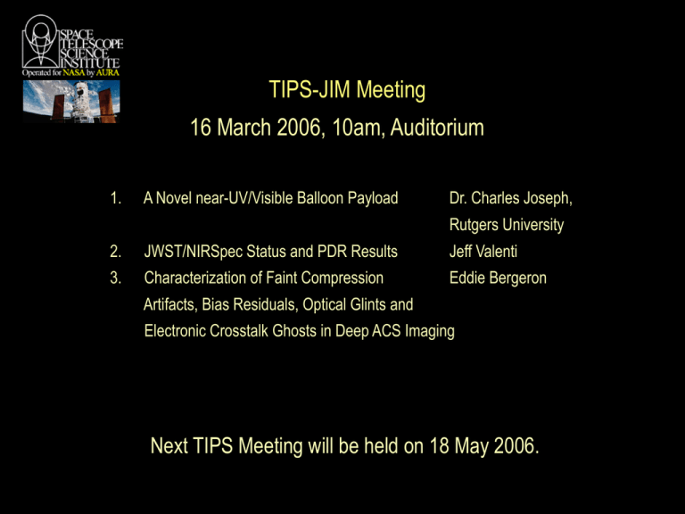
TIPS-JIM Meeting 16 March 2006, 10am, Auditorium 1. A Novel near-UV/Visible Balloon Payload Dr. Charles Joseph, Rutgers University 2. JWST/NIRSpec Status and PDR Results Jeff Valenti 3. Characterization of Faint Compression Eddie Bergeron Artifacts, Bias Residuals, Optical Glints and Electronic Crosstalk Ghosts in Deep ACS Imaging Next TIPS Meeting will be held on 18 May 2006. Why A Long-Duration Balloon? HAWK Image Quality Comparison Alt. Aperture r0 (m) FWHM(") θ0 (") τ0 (sec) 4 km CFHT 3.8m 0.18 0.7 3 0.0036 35 km 2.4 m ~250 0.048 ~600 ~5 35km 10 m ~250 0.012 ~600 ~5 Atmospheric Parameters Comparison h (km) P (mbars) T (K) ρ (gm m-3) H2O Vapor (gm m-3) 4 680 253 937 0.68 35 4.7 222 7.4 0.00011 Data from Ford et al. 2000 Presented by Chuck Joseph 26-March-06 Hierarchical Assembly through Wide-field Kinematics Novel HAWK Telescope Optical Design System is fully steerable over 0.5° x 1.5° using only tip/tilt of a 10 cm flat mirror 0.5° x 1.5° field of regard 2.2 arcmin IFOV Primary mirror 1.8 m diameter f/2.7 (from MMT) Pickoff mirror 30 x 64 cm flat near intermediate focus Secondary mirror 35 cm diameter (Used slightly off axis) Tertiary mirror 0.5 m x 1.1 m off axis asphere (long direction is out of the page) Design by CoI Jim Burge Steering mirror 10 cm flat 5° x 15° range of motion at exit pupil Focal plane f/27 system 4.2 arcsec/mm plate scale (2k x 2k x 16 µm CCD shown here) Excellent performance across the field HAWK Nominally designed so that rms wavefront error RMSWE is limited to 20 nm. Low imaging distortion (4% max at corners of field) RMS Wave Front Error in Waves 0.050 0.000 0.000 0.75 -X Field (degrees) HAWK Proposed HAWK LDB Mission Hierarchical Assembly through Wide-field Kinematics ---The Big Bang --- A consistent picture of the evolution of the Universe from the Big Bang to the present is emerging. Some data, however, suggest galaxies may not fit this model! (15 Billion Yrs Ago. z > 100) The Unobserved Realm To Be Explored by JWST First Star Formation First Galaxy Structures From the Early Universe (11 Billion Yrs Ago; z ~ 1.5) Galaxies were less well organized Galaxy Evolution To be observed by HAWK Merging Galaxies Payload to be designed & built at Rutgers U. Hierarchical Assembly through Wide-field Kinematics HDF HDF Redshift Catalog Distance (Mpc x 105) HAWK 0.7 1.2 Mission Objectives: Graphics Credit: Fanning Software Consulting Study all motions in a 10 Mpc3 Volume! Determine luminous + dark matter content as a function of internal radius and redshift. Measure empirically how galaxies evolve from an early epoch. ! (Model independent.) HAWK will pick up 100x more than HST! Observing Galaxies as a Function of Z Emission Map z = 1.35 HAWK Balloon Mission Objective: Measure luminous and dark matter in galaxies Emission Map z = 0.75 Emission Map z = 0.35 e263g14 Rotation Curves Velocity Map z = 0.75 Velocity Map z = 1.35 Velocity Map z = 0.35 HAWK LDB Balloon -- Can’t do Imaging Spectroscopy with Large Ground-based Telescopes with AO FOV on a 10 m with AO With AO HAWK FOV PSF Comparisons Bottom: 10 m good seeing Top: 10 m with AO HDF North Ground-IR have Bad Thermal Backgrounds! HAWK spatial resolution = 0.07″ Good Seeing Without AO KITE Kinematical Imaging Trailblazer Experiment Near-UV EBCCD Electron-Bombarded CCD Weight: 4 kg (2 kg Possible) c/f MAMA: 10 kg Swallow-tail Kite by D.A. Rintoul, USGS 25% QE – Solar Blind (50% Possible) c/f MAMA 10% c/f WFPC2 system efficiency 0.25% 5.6x of GALEX with 0.75 m telescope TIPS-JIM Meeting 16 March 2006, 10am, Auditorium 1. A Novel near-UV/Visible Balloon Payload Dr. Charles Joseph, Rutgers University 2. JWST/NIRSpec Status and PDR Results Jeff Valenti 3. Characterization of Faint Compression Eddie Bergeron Artifacts, Bias Residuals, Optical Glints and Electronic Crosstalk Ghosts in Deep ACS Imaging Next TIPS Meeting will be held on 18 May 2006. NIRSpec Status and PDR Results Jeff Valenti & Mike Regan 2006 March 16 TIPS/JIM Light Path PDR Objectives Assess compliance with requirements Assess NIRSpec system specifications Assess external interface definitions Integrated Science Instrument Module Microshutter Array Detector Subsystem Assess predicted NIRSpec performance Assess cost, schedule, and risk estimates PDR Format Board Technical Panels Led by ESA with NASA participation Co-chaired by NASA Independent Review Office System Structure, thermal, and mechanisms Optics Electrical and software Product Assurance Programmatic Panel PDR Timeline Dec 1 Documents delivered Dec 2 Kick-off meeting held … Panel meetings … Jan 6 Panel chairs met “Review Item Dispositions” submitted Jan 31-Feb 2 Co-location ESA/Industry ESA/Instrument Science Team Feb 9 Panel chairs reported to board Feb 15 Board met PDR Verdict NIRSpec PASSED its PDR! PDR Major Findings Microshutter technology is a risk Electrostatic discharge is a risk Create stray light control plan Include detector in EMC control plan Cool light sources used in ground tests Prevent contamination by water Manage target acquisition interfaces Test cold after observatory integration No Schedule Change JWST launch date slipped to June 2013 NIRSpec delivery date is unchanged Necessary to control ESA costs Requires timely definition of interfaces Requires timely delivery of subsystems NASA funding ISIM to support schedule Microshutter Update Technology demonstration tests Lifetime test: <5% shutters fail after 105 cycles Acoustic test: <1% shutters fail Vibration test: <1% shutters fail Radiation test: <1% shutters fail Open/closed contrast: >2000 EMC/EMI test Demonstrate ability to plug shutters in lab Stiction issue 0.5% shutter stuck open after 105 cycles Heating to 300 K causes shutter release Rogue Path Update Unbaffled telescope Sky skirts FSM and illuminates POM NIRSpec wants 9 mm increase in FSM mask NIRCam coronagraph blocked by >6 mm Outer edge of FSM mask Inner edge of NIRSpec mask Q1 Q2 Orders of Magnitude in Scale 10× Q3 Q4 10× 4×365×171 250K Shutters 10× Plate Scale Changes We must position targets in shutters Allocate 5 mas for plate scale changes Corresponds to 0.01% change in focal length Rephase primary as often as once a week TIPS-JIM Meeting 16 March 2006, 10am, Auditorium 1. A Novel near-UV/Visible Balloon Payload Dr. Charles Joseph, Rutgers University 2. JWST/NIRSpec Status and PDR Results Jeff Valenti 3. Characterization of Faint Compression Eddie Bergeron Artifacts, Bias Residuals, Optical Glints and Electronic Crosstalk Ghosts in Deep ACS Imaging Next TIPS Meeting will be held on 18 May 2006. Horizontal Striping Vertical Striping Superdark has bias “hot column” residuals in it. These don’t scale linearly with exposure time and print onto science data. Superbias images below with hot pixels removed, then smoothed to show structure bias stripes removed with bias stripes Pipeline bi-weekly superdarks show similar bias striping Other macro-scale structures in the dark are likely amplifier bias shape differences between the 1000s dark exposure and the 0s bias subtracted from it. The 1200s science exposures will have similar (but not exactly the same) residuals. Low/hi corners and vertical/horizontal gradients across the quads are most likely bias, not dark current Glint (internal optical reflection) Optical glint, possibly from an off-chip source crosses the field diagonally. Would like to characterize its behaviour (motion and intensity) so it can be subtracted from the data before drizzling. The glint in each chip was measured at 3 points along its length to get its slope and amplitude Fitting lines to the glint across both chips revealed that its is pivoting about a point near the upper left edge of chip2. A model glint image was build by shifting and rotating all the images to the same glint orientation and filtering sources. This model, masked to minimum extent then rotated, shifted and scaled, was then subtracted from each input image before drizzling. Chip 2 Chip 1 Close-up of Chip 1 Glint Residual “sky” Subtraction Since many of the residual bias/dark structures discussed previously have not been corrected by the reference files, a catch-all sigma-clipped average, source-masked sky made from all of the input images is subtracted from each image before drizzling. Some glint residual is visible here and that will oversubtract from the data, leaving a faint dark residual in the final image. This is an image of all the systematic noise remaining after the pipeline calibration Amplifier Ringing? Moderately bright star (but unsaturated in 1200s) leaves a long decaying, very faint trail in the serial read direction. The decay is slow enough to wrap around to the next row. This is similar to behaviours seen in WFPC2 and NICMOS, but much, much fainter. Its likely this is present for all bright, sharp sources, but only visible above the noise with deep imaging like UDF Correctable with a sum of exponentials in the serial read direction Electronic Crosstalk Ghosts Sources produce dark ghosts of themselves in the opposite quadrant and even in the quads of the other WFC CCDs. This is some form of electronic crosstalk (see ACS ISR 4-12, 4-13, Giavalisco 2004 for details). Even in this GAIN=2 data, the ghosts are quite prominent. In the drizzled z-band image, the ghosts are smeared by the dithering. Due to the orientations of the readout directions of the 4 WFC quadrants, the ghosts move in the opposite direction of the sources in the serial readout direction (X), but they move together in the parallel readout direction (Y). Ghosts and their sources Serial Parallel C Serial Parallel A Serial The same logic applies to all 4 quads. D Y Parallel If a source in quad D moves in +X,+Y, its ghost in quad C moves in -X,+Y. Chip2 Parallel ACS WFC readout orientations. Sources and ghosts follow the arrows. B Serial Chip1 X Flip -X,Y then copy Serial Parallel C D Y A Serial Parallel Parallel Three permutations -3 drizzles - gives you all 12 ghost quads. (3 ghosts per 4 source quads) Serial Parallel Use a trick to make drizzled images of the ghosts: Flip the quads in appropriate directions, then drizzle! Example for l-r interchip permutation B Serial Flip -X,Y then copy X Once you have high S/N images of ghosts you can either subtract the image directly, or try to build a model of the ghost behavior as a function of source - that’s the next step… Side-by-Side Comparison Original (same stretch) Cleaned Still to do: E-ghosts, better glint subtraction, amp ringing correction end transmission TIPS-JIM Meeting 16 March 2006, 10am, Auditorium 1. A Novel near-UV/Visible Balloon Payload Dr. Charles Joseph, Rutgers University 2. JWST/NIRSpec Status and PDR Results Jeff Valenti 3. Characterization of Faint Compression Eddie Bergeron Artifacts, Bias Residuals, Optical Glints and Electronic Crosstalk Ghosts in Deep ACS Imaging Next TIPS Meeting will be held on 18 May 2006.
