SGT-600 Industrial Gas Turbine
Mechanical Drive: (ISO) 25.40 MW (34,100 bhp)
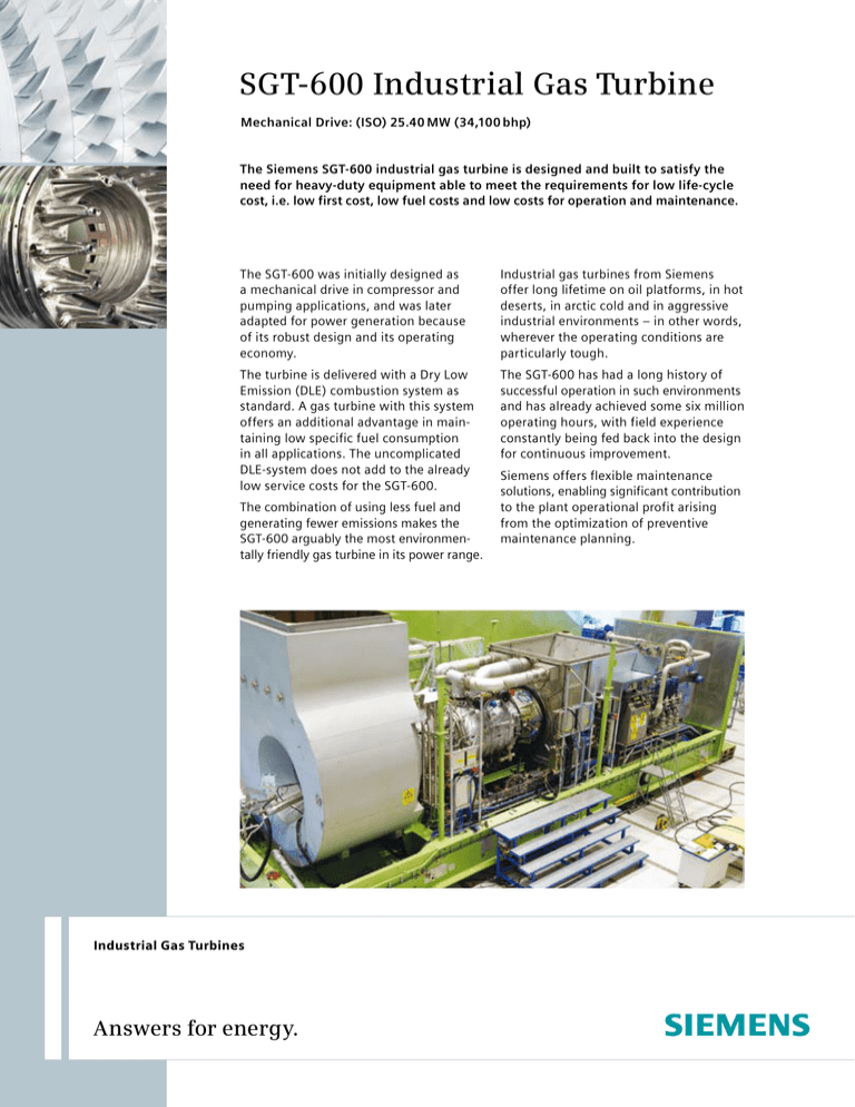
The Siemens SGT-600 industrial gas turbine is designed and built to satisfy the
need for heavy-duty equipment able to meet the requirements for low life-cycle
cost, i.e. low first cost, low fuel costs and low costs for operation and maintenance.
The SGT-600 was initially designed as
a mechanical drive in compressor and
pumping applications, and was later
adapted for power generation because
of its robust design and its operating
economy.
Industrial gas turbines from Siemens
offer long lifetime on oil platforms, in hot
deserts, in arctic cold and in aggressive
industrial environments – in other words,
wherever the operating conditions are
particularly tough.
The turbine is delivered with a Dry Low
Emission (DLE) combustion system as
standard. A gas turbine with this system
offers an additional advantage in maintaining low specific fuel consumption
in all applications. The uncomplicated
DLE-system does not add to the already
low service costs for the SGT-600.
The SGT-600 has had a long history of
successful operation in such environments
and has already achieved some six million
operating hours, with field experience
constantly being fed back into the design
for continuous improvement.
The combination of using less fuel and
generating fewer emissions makes the
SGT-600 arguably the most environmentally friendly gas turbine in its power range.
Industrial Gas Turbines
Answers for energy.
Siemens offers flexible maintenance
solutions, enabling significant contribution
to the plant operational profit arising
from the optimization of preventive
maintenance planning.
SGT-600 Industrial Gas Turbine
SGT-600 power-turbine rotor-assembly.
Technical specifications
Gas turbine
Overview
Fuel System
• Mechanical drive: 25.40 MW
(34,100 bhp)
• Shaft efficiency: 35.1 %
• Heat rate: 10,258 kJ/kWh
(7,250 Btu/hph)
• Turbine speed: 7,700 rpm (50–105 %)
• Compressor pressure ratio: 14:1
• Exhaust gas flow: 80.4 kg/s (177.3 lb/s)
• Exhaust temperature: 543° C (1,009° F)
• NOx emissions
(with DLE corrected to 15 % O2 dry)
- Gas fuel: ≤25 ppmV
- Liquid fuel: ≤42 ppmV (wet)
• Natural gas – Liquid fuel – Dual fuel
• Fuel-changeover capability
at full and part load
• Gas-supply pressure requirement:
24.5 bar(a) ±0.5 bar (355±7 psi(a))
Axial Compressor
• 10-stage axial flow compressor
- 2 stages variable guide vanes
• Electron-beam welded rotor
Combustion
• 18 dual-fuel 2nd generation
Dry Low Emissions (DLE) burners
• Welded annular sheet metal design
Compressor Turbine
• 2-stage axial flow compressor turbine
- Both stages are air-cooled
Emissions control
• DLE combustion system
• Water injection for NOx-reduction
during liquid fuel operation in
DLE combustor
Bearings
• Tilting pad radial and thrust
• Vibration- and temperaturemonitoring
Lubrication
• Lubricating oil tank located in
package base frame
• Two main lube oil circuits,
low pressure and high pressure
• 3x50 % HP and 3x50 % LP AC-driven lube oil pumps with DC backup
Starting
• Electric VSD start-motor
Power Turbine
Control System
• 2-stage free power turbine, uncooled
• Interlocking shrouds
• Siemens Simatic S7
• Distributed inputs/outputs
Key features
Robust industrial design
Excellent operational availability
and reliability
Excellent DLE experience
Low emissions – DLE ≤25 ppm NOx
Dual-fuel capability
Wide range of fuel capability
Long-term efficiency – low deterioration
Low life cycle cost
Workshop tested
Maintenance
No need for special workshop
maintenance
24-hour gas generator exchange or
on site maintenance
Modular build-up for easy maintenance
on site
Standardized concepts for maintenance
planning
Condition-based maintenance
Extended time between overhaul
when running on part load
Low deterioration and service cost
Gas turbine can be removed on rollers
through the maintenance doors
Horizontal split compressor casing
Compressor drive installation in Edjeleh, Algeria.
Four units were installed at a pipeline compressor station in Kondratki, Poland.
Package
Customer Support
Key features
Key features
Compact layout
Flexible installations based on standardized
package solutions
Gas turbine and main auxiliary systems are
mounted on a common base frame
Skid-mounted with single-lift capacity
Pre-commissioned at the Siemens workshop
to reduce time at site
Simple on-site works due to flexible
package design
State-of-the-art control system fulfills all
requirements for control and safety
Same footprint as the SGT-700 gas turbine –
interchangeable in same package
Height to top of package: 11.9m
Global support network of Authorized
Service Centers
Emergency service – 24 / 7 specialist
helpdesk
Full field service
Full diagnostic support, remote
monitoring
OEM modernizations and upgrades
In-house or on-site training programs
Range of maintenance and service
contracts available
SGT-600 standard driver package
1 Combustion air inlet
2 Enclosure air inlet
3 Lube oil system
4 Combustion exhaust
5 Enclosure air outlet
6 Core engine
Wi
dth
:
4.1
m
Gas
ngth:
le
ckage
e pa
turbin
11.6m
SGT600 Performance
28
En g
le t
in e in
tem
tur
per a
e (º C
30
)
-30º C
-15º C
0º C
Nominal shaft power, MW
26
15º C
10,435
24
10,588
30º C
22
10,910
20
Sp ec ific he at
inp ut, kJ/ kW
h
18
11,250
45º C
11,614
16
St a
Nominal shaft power at nominal PT speed, MW
30
28
En g
ine
nda
inle
26
rd P
t te
TN
mp
oz z
er a
le
ture
(º C
)
24
22
20
18
16
12,000
12,414
12,859
14
4000
5000
6000
7000
14
8000
-40
-20
Power turbine rotor speed, rpm
Nominal performance
Power and specific heat input and speed
0
20
40
Engine inlet temperature, ° C
Power output at turbine coupling and
engine inlet temperature
SGT-600 Mechanical drive performance
Conditions/assumptions:
Direct drive – no output gearbox. Natural gas fuel.
Altitude:
Sea level Ambient pressure:
Inlet ducting loss:
0 kPa Relative humidity:
Exhaust ducting loss: 0 kPa Power turbine design speed:
Natural gas fuel.
101.3 kPa
60 %
7,700 rpm
Specific heat input is drawn for base load but is approximately correct for part load at corresponding speed/temperature.
Published by and copyright © 2010:
Siemens AG
Energy Sector
Freyeslebenstrasse 1
91058 Erlangen, Germany
Siemens AG
Energy Sector
Oil & Gas Division
Wolfgang-Reuter-Platz
47053 Duisburg, Germany
Siemens Energy, Inc.
10730 Telge Road
Houston, Texas 77095, USA
Siemens Industrial Turbomachinery AB
Slottsvaegen
SE-61283 Finspong, Sweden
www.siemens.com / energy
For more information, please contact
our Customer Support Center.
Tel: +49 180 524 70 00
Fax: +49 180 524 24 71
(Charges depending on provider)
E-mail: support.energy@siemens.com
Oil & Gas Division
Order No. E50001-W430-A110-X-4A00
Printed in Germany
Dispo 34806, c4bs 7447, P WS 03102.5
Printed on elementary chlorine-free bleached paper.
All rights reserved. Trademarks mentioned in
this document are the property of Siemens AG,
its affiliates, or their respective owners.
Subject to change without prior notice.
The information in this document contains general
descriptions of the technical options available, which
may not apply in all cases. The required technical
options should therefore be specified in the contract.


