s
All Electric Driven Refrigeration Compressors in LNG Plants Offer Advantages
by Fritz Kleiner, Siemens AG, Industrial Applications, Oil & Gas Business Unit,
and Steve Kauffman, Shell Development (Australia) Pty. Ltd., LNG & GTL
Abstract
Refrigeration turbo compressors in modern
LNG liquefaction plants are traditionally driven
by industrial heavy duty gas turbines. With an
ongoing industry trend towards larger train
sizes, and more emphasis placed on higher
energy efficiency and lower greenhouse gas
(GHG) emissions, the use of very large electric
motors to drive the compressors becomes of
increasing interest and the first “all electric
driven” LNG plant will soon go into operation
in Norway. Economic and operational advantages of this alternate drive concept are
discussed for the owners & operators of LNG
liquefaction plants, a typical comparison study
of the two alternatives is shown, and some
details of the electrical drive technology
employed are presented.
Introduction:
Evaluating electric drive LNG processes has
moved on from when the concept of using synchronous motors and combined cycle power generation plants was introduced at the Doha Conference on Natural Gas in 1997. Logically at that
time, evaluation efforts were directed at technical
aspects, in particular, focussing on technical risk
as well as economic comparisons. Studies by
ChevronTexaco [1] and Shell Global Solutions
corroborate the view that such risks are well known
and manageable through detailed design. Subsequent further development of the motor drive
system by a number of (European) manufacturers,
specifically for LNG application, validates this view
[3] [4]. Most conclusively however, the successful
manufacturing, testing and full compressor/drive
string testing now completed for the Norwegian
Snøhvit project has shifted owner/operator’s
interest in the electric drive from risk assessment
to opportunity framing, especially if the total
refrigeration system, including the power plant,
forms the basis for performance guarantees.
Deliberately putting the remainder of the LNG process plant aside, the comparison focuses on the
two driver concepts and their characteristics. And
to make a sound comparison of the two driver alternatives – traditional mechanical vs. evolutionary
electrical – one must list the individual properties of
these designs.
All gas turbines, by nature of their physics and
design, have inherent limitations when compared
to equivalent electric motors:
• high thermal and mechanical stresses with
resulting lifetime reductions of certain components and re-occuring service requirements
• complexity and sensitivity of machines due to
numerous very tight clearances and tolerances
between stationary and rotating parts
• available only as type-tested standardized
products with given output ratings and limited
speed range
• relatively poor efficiency and high greenhouse
gas emissions when compared to combined
cycle
• inability to start by itself and to accelerate
loaded compressors (single shaft only)
• reduced power output at high ambient temperatures and poor part load efficiency
• limited vendor competition.
None of the above applies to electric motor
variable speed drivers of equivalent rating & performance, and this is the key to considering
electric motor compressor drivers as a viable alternative for new installations.
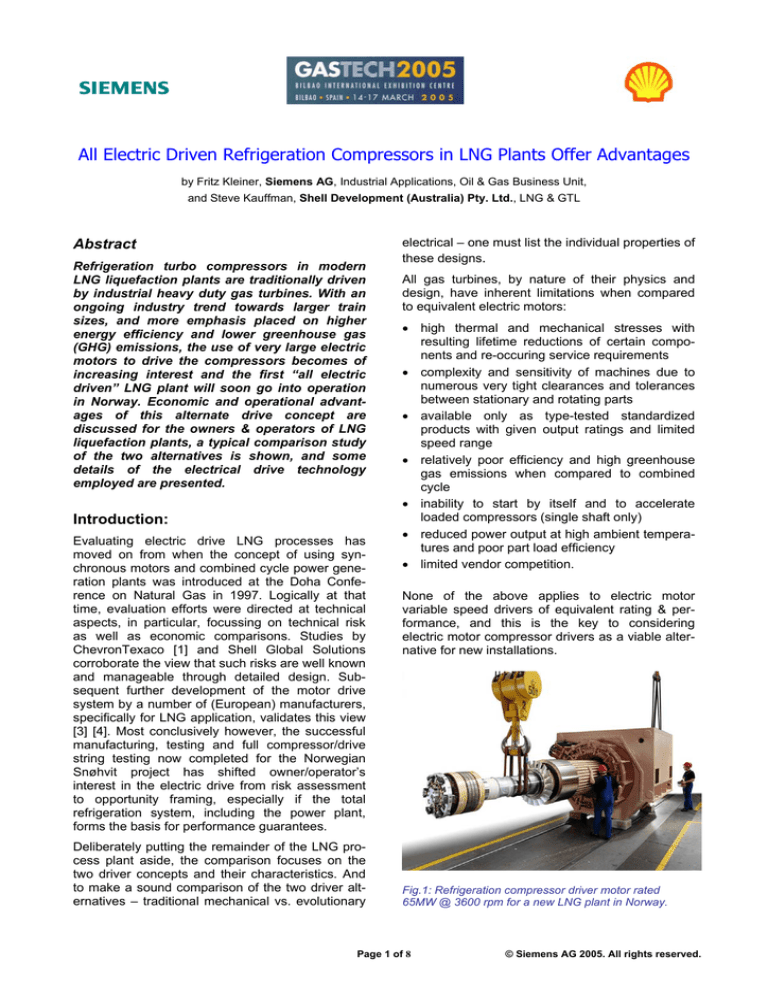
Fig.1: Refrigeration compressor driver motor rated
65MW @ 3600 rpm for a new LNG plant in Norway.
Page 1 of 8
© Siemens AG 2005. All rights reserved.
Economic & operational advantages of
electric motor drivers
For Shell Development Australia (SDA), the interest in electric drives emerged primarily from the
observation that high overall efficiency would be
achieved simply in this drive concept because
waste heat from all gas turbines would be exploited while retaining independence between process
and utility equipment and systems. This interest is
further motivated by the potential to reduce both
cost and GHG emissions; cost for obvious
reasons, and emissions to meet company policy
and Government Strategy in Australia, both having
a clear focus on emissions reduction and energy
efficiency (i.e. continuous improvement). Although
not defined prescriptively in the legislative environment, the Western Australia Sustainability Strategy
(2003) has clear objectives for a four-fold increase
in industry eco-efficiency by 2020.
A high level comparison of direct and electric drive
concepts identified the following opportunities as
substantive reasons to examine electric drives
more closely:
• Utilise waste heat from all gas turbine exhausts,
thus achieving lower GHG emissions, in a
simple way and without complicating the
equipment used in the process area.
• Eliminate asset downtime and shut down/
maintenance costs associated with gas turbine
drive maintenance.
• Phase costs associated with combined cycle
capability to a later date such as an expansion
of the complex.
• Reduce fuel gas consumption, both from an
OPEX perspective but also as a means to defer
subsequent upstream drilling.
• Segregate combustion and convective heat recovery equipment from the high pressure liquid
hydrocarbon equipment in the process area.
• Reduce flaring by avoiding refrigerant depressuring and enabling quicker re-starts.
More detailed assessment of these opportunities
demonstrates that an electric motor variable speed
drive (VSD) of equivalent rating is significantly less
expensive to buy & operate than a gas turbine.
Additionally, the installation cost of a gas turbine
direct drive in an LNG facility is about double its
cost as a generator drive. Infrastructure improvements at the site itself can increase the price tag of
the electric system, but not dramatically. In very
large installations, the construction of power transmission systems or even an associated power
plant may be justified if the „Total Cost of Ownership“ is considered and not only the capital
investment for the LNG plant.
Electric drive systems are sized for the maximum
average ambient, or cooling water temperature –
up to 40°C (air) and 32°C (water), respectively, no
de-rating is required. Full power is instantly available over the entire temperature & speed range,
and the number of successive and cumulative
start-stop and load cycles is generally uncritical.
Electric motor variable speed drives in the upper
Megawatt (MW) power range have energy efficiencies >95% – over the entire useful speed range,
typically 80...105% of rated speed. Even if the
energy conversion in the power plant is taken into
consideration, the electric drive’s efficiency is typically better than that of GT direct drives due to the
higher efficiency of the large C.C. power plant.
Mainly due to low thermal and mechanical stresses
in the motor, and no wear parts in the drive system*), service & maintenance expenses of electrical drive systems are only a fraction of those encountered for GT drivers: Under certain assumptions, there is no scheduled maintenance for periods up to 6 years of continuous operation, and
even after that no costly parts need to be replaced.
Full power is instantly available upon issuing the
START command, regardless of the ambient and
motor temperature, and the number of successive
starts is also unlimited: Unlike a fixed-speed electric motor that is started „across the line“ (DOL
starting) the variable speed drive does not draw
more than rated current from the power system
during starting, and is thus not thermally and/or
mechanically stressed beyond its rated duty.
And the electronically controlled starting torque is
always sufficient to start even a fully loaded
compressor – a valuable asset in case of process
trips because the compressor circuit does not have
to be depressurized (no flaring or loss of
refrigerant) and the cryogenic process elements do
not warm up.
Electric drive systems of this class are always
custom engineered for the application on hand,
allowing the compressor to be optimized in capacity & speed for the process on hand, and not being
limited by a given GT rating. In case of twin compressor bodies, these can often be arranged on
either side of the motor shaft, providing ready
access to the inner bundles, bearings, and seal
cartridges of vertically-split compressors, without
disturbing the basic alignment of the compressor
bodies. This feature is the key to larger LNG train
capacities since electric motors can readily be built
up to today’s limit ratings of the compressors.
________________________________________
*) A properly lubricated sleeve bearing is not considered a wear
part and does not require regular service
Page 2 of 8
© Siemens AG 2005. All rights reserved.
The Turborotor Motors
Brushless synchronous motors with solid steel twopole turbo rotors are the design of choice for high
performance applications such as LNG liquefaction
– they have been in service for decades in various
industries to drive centrifugal pumps and compressors, in ratings up to 40 MW and speeds to 6600
rpm (not in this combination!) and their construction is practically identical to that of turbo generators in power stations – which have output ratings
exceeding 600 MW.
In 2003 Siemens built and load-tested the first „all
electric“ refrigeration compressor drivers for a new
LNG liquefaction plant, with rated powers of 65
MW and 32 MW at 3600 rpm, respectively, and
such drives are offered in ratings exceeding 80
MW at the same speed.
ceeding 45°C, mechanically refrigerated chilledwater sets may have to be used. Open ventilated
motors, such as WP or IPR enclosures, are generally not used in extreme environments in order to
protect the winding insulation systems from contaminants in the cooling air.
Hydrodynamic pedestal-type sleeve bearings with
fixed or tilting pads and forced oil lubrication are
standard, even though endshield mounted sleeve
bearings can be used to advantage in certain cases. Rotor dynamics are typically in-line with API
546 (synchronous motors) or API 617 (centrifugal
compressors) requirements and generally the compressor lube oil circuit is also used for the motor.
Couplings between motor and compressor shafts
are mostly multiple-diaphragm dry types from reputable vendors, whereby special attention is given to
short-circuit moments. Flanged couplings with quilt
shaft have also been used, but stepped cylindrical
shaft ends for hydraulic shrink fit of the coupling is
the rule. It is normal practice to mount both the
compressor and the motor on a common baseplate
or skid, and to test the entire assembly under load
in the factory prior to dispatch to the job site. Full
load performance tests of such compression systems can be performed up to about 80 MW, with
most job equipment being part of the test, thus
reducing the installation time & risk considerably.
The Drive
Fig.2: Theoretical limit rating curves for 2-pole compressor drive motors. Note: Any specific rating near these
limit curves must be verified for an actual application
For lower power ratings the shaft speed can be increased somewhat; the present limit being the circumferential rotor speed of 200 m/s and rotordynamic considerations: Flash-gas compressors in
LNG plants are good examples and include a 17
MW brushless synchronous motor operating at
speeds up to 6660 rpm and 23 MW depletion
compressor drivers with speeds up to 6300 rpm.
Totally enclosed horizontal air-water cooled motors
(TEWAC) in class of protection E Ex(p) IP54 acc.
to IEC are typically used for compressor applications in Zone 1 or 2 hazardous environments, certified by the authority having jurisdiction for the project site. If no cooling water is available on site,
totally enclosed air-air cooled machines (CACA)
can be used in some cases but for extreme ambient conditions with temperatures frequently ex-
To convert the fixed power line frequency (50 or 60
Hz, depending on country of installation) into the
variable voltage & frequency pair required to operate the synchronous motor over the specified
speed range, a solid-state frequency converter is
used, called by some in the industry „the drive“.
Whereas there is a variety of „drives“ on the
market for lower power ratings, there is only one
proven frequency converter employed for power
ratings above about 20 MW, the load commutated
inverter, or LCI drive.
Fig.3: One-half of a 65 Megawatt LCI-type frequency
converter or „drive“ for the motor shown in Fig.1.
Page 3 of 8
© Siemens AG 2005. All rights reserved.
This simple, robust and time tested frequency converter employs readily available disk-type thyristors
(or silicon controlled rectifiers, SCRs) as solid state
power switching elements. They are mounted in
standardized equipment cubicles for installation indoors, or in purpose-built power centre modules
outdoors.
used and they, too, can be installed inside prefabricated power modules, ready for connection. The
sizing, building and protection of harmonic filters is
routine for experienced drive system suppliers and
they are safe and reliable passive subsystems,
both in indoor & outdoor installations.
Heat losses of the power semiconductors are removed from the converter via a closed-loop deionized water circuit that in turn can be recooled to
ambient air, or to an external cooling water loop.
Testing
The entire drive system, including motor and auxiliaries, is closed loop controlled and fully protected
by a microprocessor based control system. Due to
its robustness and smart protection functions it
meets highest availability requirements without the
need for excessive redundancy.
Auxiliary Systems
To match the drive’s input voltage to the power line
voltage on site, an oil-filled outdoor converter
transformer is required. This isolation transformer
also provides for the 12-pulse line reaction of the
converter towards the power system, and for fault
current limitation in the power semiconductors,
avoiding fuses in the power circuits altogether.
This transformer is connected via power cables to
the frequency converter, and screened cables also
link the „drive“ to the motor.
In the motor, the same 12-pulse circuits reduce the
torque ripple, which is produced by the non-linear
frequency converter and is superimposed on the
mean torque of the motor, to levels uncritical for
the compressors: A complete torsional analysis of
the rotating string is nevertheless performed to
identify and quantify potentially harmful harmonic
torque amplifications, and to size the shafts and
couplings of the machines.
The frequency converter with its cooling & control
systems, LV switchgear, MCC and UPS systems,
and the local operator interface are typically installed in prefabricated power centre modules (containers) at the manufacturers location where they
are also tested and pre-commissioned prior to
shipment. These custom engineered modules are
unconditionally suited for installation outdoors in
the climate zone specified, if necessary with full
climate control, and meeting local building codes.
With this modular building concept, the number of
shipping colli and the amount of installation work
on site are minimized. This module concept also
facilitates the various performance and load tests
typically specified for such compression systems.
LCI-type frequency converters produce power line
harmonics as a side effect. To maintain the limit
values prescribed by the utility company or by
National Codes, harmonic filters may have to be
LNG plants are mostly located in remote areas of
the world and in extreme climate zones. Lack of
performance or malfunctions of subsystems after
installation can have grave financial consequences
and complete testing of compression systems at
the manufacturer’s location is thus normal. To
make sure that the electrical drive system performs
as specified prior to this full-load test at the compressor manufacturer's test facility, they can be
load-tested as well in the motor factory: With two
or more identical drive systems on order at the
same time, they can be tested at or near full load &
speed in the so-called back-to-back mode, i.e. one
unit operates as motor, the other one as generator.
Fig4: Back-to-back performance test of two 65MW
compressor driver motors in the Berlin motor plant.(The
associated „drives“ are located outside the building)
Such tests are expensive and time consuming but
they can be performed by major drive system
suppliers – the modular construction principle
described above greatly assists to this end.
The associated power plant
Electric motors driving refrigeration compressors in
LNG plants need electricity – lots of it and on an
uninterrupted basis: The availability of the drive
and thus the refrigeration system is practically
identical to that of the power transmission system,
or the associated power station. LNG plants most
always being located far away from a solid infrastructure, these power plants typically operate in
an island mode, i.e. without being connected to a
transmission grid. And since the turbo generators
in the power plant are driven by gas turbines –
typically much larger ones than used for direct
Page 4 of 8
© Siemens AG 2005. All rights reserved.
compressor drivers – and these engines also require maintenance every so often, an extra turbo
generator is installed for 5 or 6 year uninterrupted
power supply to the LNG process – following the
so called n+1 principle. This, of course, is a burden
on the capital budget for the LNG project and it
may be advantageous to assign the financing, construction & operation of the power plant to an independent power producer (IPP) company that then
provides the needed Kilowatt-hours „over the
fence“ to the LNG plant on a long-term contract
basis, in exchange for fuel gas and a fixed kWhrate. Such IPP plants can then additionally supply
electric power to neighbouring communities or
industries, often a strong incentive for local governments to approve the LNG project – and the reduced total greenhouse gas emissions of an „all electric“ LNG plant can be another incentive for political decision makers to approve the project.
Depending on the individual manufacturer’s concept, power plants dedicated to „all electric“ LNG
plants may comprise of 3 or more large turbo generators per LNG train, operating in parallel at part
load during normal operation. For maximum efficiency and minimum total emissions, they are preferably planned as a combined cycle power plant,
utilizing the waste heat from the GTs in heat
recovery steam generators (HRSGs) that in turn
feed a steam turbo generator set – standard,
proven and commercially available technology.
Energy efficiencies of 50% can be achieved with
these plants, taking account of the part load
operation and the use of relatively low grade fuel
gas with N2 contents of 25% and more. This capability, combined with the requirement for utmost
availability of the turbines, does typically not result
in the use of the most modern GTs but in the
selection of the most robust engines with the
longest service history & maintenance intervals.
system: The unscheduled outage of a compressor
or a vsds (initiated by the process itself or by the
rotating string’s own protective systems) is considered less critical and service can typically be
restored within a short time because the vsds can
always re-start the fully loaded compressors.
Compensating for the unexpected loss of a turbo
generator in the power station requires a quick redistribution of the total electrical load onto the
remaining running turbo sets, without violating the
voltage & frequency limits of the electrical system,
or the speed limits of the turbines and compressors, respectively – a demanding task. With suitable steam reserves, and specific control actions in
the power plant and the compressor & drive
systems, this situation can be coped with,
generally without losing the refrigeration process.
Computer simulations of the thermodynamic, electrical, and mechanical systems are used to identify
weak spots during the design phase, and performance guarantees should be provided for the
entire refrigeration system.
Case study
Being able to maximise the various opportunities
with electric drives discussed so far, is not simply a
change of driver type. Process type, process configuration and driver choice must all be considered if
the benefits suggested are to be fully exploited.
While this wider topic is not covered in this paper,
the resulting quantification of these benefits is provided. The case study used liquefaction processes
configured to suit direct or electric drives and
designed specifically to meet the same (nominal)
project parameters. Cost, reliability and environmental performance were assessed, both as single
train and multi-train facilities. The multi-train aspect
of the study was important to emulate a focus on
continuous improvement, the reasons for which
are explained later. A nominal gas composition
was chosen (962 BTU/scf C1-C5 content and
around 7% CO2).
Fig.5: Thermal schematic diagram of a combined-cycle
power plant to supply an „all electric“ driven LNG plant in
an island-mode of operation.
Fig.6: Comparison of direct and E-drive solutions as
used in the study: C3MR vs. DMR process
If one of the turbo generators is lost unexpectedly
during normal plant operation, this constitutes the
most severe disturbance of the refrigeration
The direct drive concept used (abbreviated as Ddrive) entails the well known application of two
Page 5 of 8
© Siemens AG 2005. All rights reserved.
Frame 7 industrial HD gas turbines, utilising either
propane or mixed refrigerant for the pre-cooling
cycle and a lighter mixed refrigerant for the main
cryogenic cycle (i.e. typical C3MR and dual-mixed
refrigerant type processes). The turbines are each
equipped with a 20MW starter/helper motor and
the pre-cooling and main cryogenic cycles are
arranged in series. Waste-heat is recovered from
the precooling gas turbine exhaust., Process heat
is distributed by a conventional hot oil or hot water
system.
The electric drive concept (E-drive) entails the
LNG Gamechanger configuration of Shell Global
Solutions, which deploys a similar dual-mixed refrigerant process, and arranges the motor-compressor sets partly in parallel. Waste-heat is similarly
recovered via the power-generation turbine exhausts. Additional harnessing of waste heat to support combined cycle facilities was also explored.
Economic drivers for electric drive
The cost/benefit equation for electric drive is summarised in Table 1 for a train size of 5 mtpa. Cost
has been expressed as the “incremental” EPC cost
difference between E-drive and D-drive for a train
delivering the same daily LNG production. This
approach is quite robust because the equipment
involved and utility systems design remains the
same in both concepts. It is only size of the utility
systems which differ. Comparing this result to the
work of Shu et al [1] for a comparison of 4 mtpa
trains, which reached a similar conclusion, it is
postulated that the higher electrical load needed
for the 5 mtpa D-drive concept (i.e. being a hybrid
electric/direct drive concept), only enhances the
advantages to be realised from a full E-drive
arrangement..
COST – Additional cost of E-drive train
<US$ 20M
Main equipment differences
Fig.7:Moving from D-drive to E-drive entails the enlargement of the electric motor and the elimination of the GT.
Both concepts have the same number of rotating
equipment per train; 4 drivers and 4 compressors.
Both concepts also require the same individual
components to transmit electricity from generation
to mechanical power, either as a helper drive in the
D-drive case, or as main drive in the E-drive case.
In fact, the 5 mtpa direct drive train has evolved into a type of hybrid direct/electric concept. As such
it already uses the identical drive system designs
as employed for E-drive.
The key differences between the concepts are the
up-scaling of motors from 20 MW to 65 MW, and
the elimination of the gas turbine driver, in some
cases a split casing type compressor, in other
cases an axial compressor and the large shaft
linking driver and compressors as a single rotating
string. With fewer components and more robust
drivers the E-drive has the potential for significantly
improved operating reliability and availability.
Electric drive train:
Direct drive train:
360 MW centralised power
plant inclusive of N+1
sparing philosophy
110 MW centralised power
plant inclusive of N+1
sparing philosophy
Centralised waste heat
recovery supporting hot oil
or hot water heat
distribution system.
Local waste heat recovery
from precooling gas turbine
supporting hot oil or hot
water heat distribution
system
Variable speed motor drive
systems
Gas turbine plus helper
motor drive systems
Larger electrical distribution
and auxiliary systems
Smaller electrical distribution
and auxiliary systems
ANNUAL BENEFIT (total of items below)
US$ 34.1M
Minimum ten (10) additional on-stream days
per year, which is around 150,000 tonnes p.a
LNG at constant daily capacity. Priced at
US$ 3.5/MBTU f.o.b.
US$ 29.6M
Reduced maintenance and shutdown costs
averaged over 6 year maintenance cycle as
typically used for direct drive plants.
US$ 1.8M
Reduced fuelgas by 5%, priced at US$ 1.0/
MBTU.
US$ 2.1M
Reduced emissions and losses by around
100,000 t.p.a CO2e.
US$ 0.6M
Table 1: Cost/benefit tabulation of D-drive vs. E-drive in
large LNG plants
However, because the electric drive configuration
at 5 mtpa is far from any equipment size constraint, it retains potential to be larger without any
change to configuration, technical step-out, or
equipment type deployed. To study this potential
economy of scale, three designs were made and
compared; a 5 mtpa direct drive (as a datum) and
two electric drive options, one at 6 mtpa and the
other at 7.5 mtpa. The latter corresponding to a 65
MW motor/compressor string, seen as a logical
analogue to support an upper limit for study
purposes. Power generation in the electric drive
Page 6 of 8
© Siemens AG 2005. All rights reserved.
cases included co-generation of electricity and process heat. The option of combined cycle generation was explored as a continuous improvement
feature of an expanding facility.
ii) In the long term, the centralization of power
generation in E-drive will position the complex
to best accommodate fluegas treatment technologies if and when their viability emerges.
A detailed cost method was adopted to accurately
assess the benefits with changing train size. Heat
and material balances were developed with individual equipment sizing and electrical line-lists used
to cost major items consistently in all designs.
Build-up to Total Installed Cost was carried out by
Shell Global Solutions with cost differences between options being validated by separate engineering services and cost methodology being
externally audited to enhance confidence in the
study results.
The study addressed only medium term considerations, hence did not quantify long term costs
related to fluegas treatments. A long term perspective has been explored by others e.g. Kikkawa &
Lui [2] when examining the potential for zero emissions in the LNG supply chain, and this advantage
for E-drive remains noteworthy and significant in
the context of future capital investment for
emissions reduction.
A key observation was that the 2 x Frame 7 direct
drive design could, at a stretch, reach just over 5
mtpa while the electric drive could approach 7.5
mtpa. Results demonstrated that the specific cost
of a single E-drive train can be expected to continue to decline with increasing train size, reaching
some 20% lower than the direct drive datum. More
importantly, this allows the capacity of a single Edrive train to be tailored specifically to the aspirations of owners.
It is the option in the E-drive concept to phase-in
the adoption of combined cycle benefits to accompany economic advantages from brownfields
expansion, that is particularly advantageous to an
owner in the medium term.
This flexibility is achieved with little regret or preinvestment penalty and allows a venture to pursue
cost minimization when getting established, and
GHG minimization when building to eventual plateau operation. The corollary for the D-drive is to
commit to an “acceptable” compromise between
cost and energy minimization at the greenfields
phase since little scope exists to retrofit future
improvement.
Figure 9 quantifies the value of this choice for
owners by showing study results for two expansion
paths, one for a direct drive facility, the other for an
electric drive, each arriving at the same plateau
capacity of circa. 15 mtpa.
Fig.8: Capital efficiency is improved with larger train
sizes using E-drive concepts and allows owners to select
any train size as best fits the opportunity. Example:
Single train greenfields development with co-generation
of process heat & power.
Starting with the direct drive, where the single train
data presented earlier is provided for reference,
Figure 9 shows the cost efficiency generated by a
two-train greenfields project and the impact to both
cost and GHG efficiency if waste heat recovery is
extended to allow steam to also provide motive
power to the cryogenic compressors.
Continuous Improvement
Returning to earlier remarks relating to energy efficiency, focus in Australia on managed programs of
improvement continues to grow. With reporting of
greenhouse emissions to the Australian Greenhouse Office, industry performance is increasingly
available publicly. Accordingly, the need to demonstrate the application of company policies of continuous improvement in environmental performance
is becoming increasingly important. In this regard
two differences between the direct and electric
drive technologies are particularly relevant:
i) In the medium term, E-drive has the potential to
phase-in continuous improvement via a later
conversion to combined cycle, and
Fig.9: High-capacity E-Drive shows specific cost and
GHG advantages in future expansion scenarios
Page 7 of 8
© Siemens AG 2005. All rights reserved.
Use of “carbon tax” and “As Low As Reasonably
Practicable” (ALARP) principles is typical to decide
the appropriate compromise between minimum
cost, point 2D, and minimum GHG, point 2D*.
However, once the configuration is chosen, little
scope exists to improve energy performance when
adding duplicate trains. Thus, while cost improvements are achieved with brownfield expansions,
point 3D*, GHG improvements are not.
The electric drive option, with 7.5 mtpa trains
shown as point 1E, achieves very similar greenfield characteristics, and with the option to convert
the co-generation power plant used for single train
operation to a combined cycle plant when a
second train is added, the expansion plan can
achieve substantial cost and GHG improvements,
point 2E.
Hence from a medium term perspective, an E-drive
plant operating at 15 mtpa (2 trains) achieves a
specific cost approximately 10% lower than a
direct drive plant operating at 15 mtpa (3 trains),
whilst achieving some 13% lower GHG emissions.
These benefits, being around $300M and 750,000
t.p.a CO2, are significant incentives to contemplate.
• process train sizes of >5 mtpa benefit most
from the E-drive concept, especially if environmental constraints must be observed,
• the flexibility to later engineer combined cycle
schemes allows for effective cost and environmental improvement plans to be adopted.
References
[1] “Analysis points to electric-motor drivers for Angola LNG”,
Steve Shu (ChevronTexaco) and Malcolm Harrison (Foster
Wheeler Energy Limited) in Oil & Gas Journal, Oct. 7, 2002.
[2] “Zero CO2 Emission for LNG Power Chain”, Yoshitsugi
Kikkawa (Chiyoda) and Yu-Nan Lui (Air Products and Chemicals Inc.) at LNG13 conference May 14-17, 2001 in Seoul.
[3] “Increased power and efficiency of LNG refrigeration
compressor drivers”, F. Kleiner, S. Rausch, J. Knabe (Siemens
AG), in Hydrocarbon Processing Magazine Jan. 2003
[4] “Electric motors to drive the largest turbocompressors”, Fritz
Kleiner (Siemens AG), CompressorTechTwo March-April 2002.
The authors:
Conclusion
Considering these advantages, the electric motor
variable speed drive is in many cases a viable and
economically attractive alternative to the mechanical gas turbine driver for centrifugal refrigeration
compressors. With competitive & reliable electric
power available at or near the jobsite, or from an
associated power plant, this alternative should be
evaluated at a very early stage of any new project.
Several reputable manufacturers are experienced
and qualified to engineer & supply integrated refrigeration systems, alternatively with gas turbines or
electric motor compressor drivers, including the
compressors themselves, and the power plant, or
just parts thereof.
Finally, the key advantages of the „all electric“
drive system in comparison to traditional GT
drivers are repeated:
• continuous process operation is possible for six
years with expected availabilities of the refrigeration compression system (including the
power plant) approaching 360 days,
• installed and operating costs can be significantly lower; IPP schemes are available to
reduce initial investment,
• very little maintenance in the process area and
few operational spares required on site,
• custom-engineered drivers up to 80 MW@3600
rpm with no power reduction at elevated
temperatures are available and can be fully
load tested together with the compressors,
Fritz Kleiner is a merchant marine officer and communications
engineer by education. He is with Siemens for 37 years and
served in various locations and functions, ranging from service
and sales engineer to manager international projects in the
USA, and project manager for large industrial drive systems in
Germany. He specializes in Megawatt size electric motor variable speed drive systems for the process industry and today is
director business development electrical drive systems for turbo
machines in the oil & gas industry of Siemens AG, PG Industrial
Applications, in Erlangen, Germany. You can reach him at
fritz.kleiner@siemens.com
Steve Kauffman is currently the Senior LNG Advisor with Shell
Development Australia. He became involved in the LNG business in 1985 and in recent years, as a Consultant in the LNG
and Gas processing group of Shell Global Solutions International BV in The Hague, has been responsible for the technical integration of various LNG developments, including Shell’s Floating LNG and Electric Drive concepts. He has also served as
HSE Manager and Economics/Scheduling Manager for Shell
Australia's Geelong refinery. He holds a Bachelor of Chemical
Engineering degree (1981) from Melbourne University. You can
reach him at steve.kauffman@shell.com
Page 8 of 8
© Siemens AG 2005. All rights reserved.

