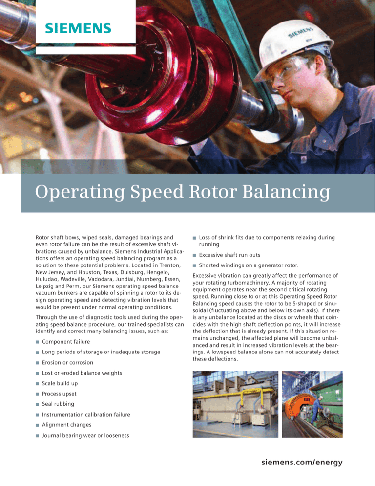
Operating Speed Rotor Balancing
Rotor shaft bows, wiped seals, damaged bearings and
even rotor failure can be the result of excessive shaft vibrations caused by unbalance. Siemens Industrial Applications offers an operating speed balancing program as a
solution to these potential problems. Located in Trenton,
New Jersey, and Houston, Texas, Duisburg, Hengelo,
Huludao, Wadeville, Vadodara, Jundiai, Nurnberg, Essen,
Leipzig and Perm, our Siemens operating speed balance
vacuum bunkers are capable of spinning a rotor to its design operating speed and detecting vibration levels that
would be present under normal operating conditions.
Through the use of diagnostic tools used during the operating speed balance procedure, our trained specialists can
identify and correct many balancing issues, such as:
Component failure
Long periods of storage or inadequate storage
Erosion or corrosion
Loss of shrink fits due to components relaxing during
running
Excessive shaft run outs
Shorted windings on a generator rotor.
Excessive vibration can greatly affect the performance of
your rotating turbomachinery. A majority of rotating
equipment operates near the second critical rotating
speed. Running close to or at this Operating Speed Rotor
Balancing speed causes the rotor to be S-shaped or sinusoidal (fluctuating above and below its own axis). If there
is any unbalance located at the discs or wheels that coincides with the high shaft deflection points, it will increase
the deflection that is already present. If this situation remains unchanged, the affected plane will become unbalanced and result in increased vibration levels at the bearings. A lowspeed balance alone can not accurately detect
these deflections.
Lost or eroded balance weights
Scale build up
Process upset
Seal rubbing
Instrumentation calibration failure
Alignment changes
Journal bearing wear or looseness
siemens.com / energy
The Duisburg operating speed
balance facility specifications
are as follows:
The Hamilton, New Jersey
operating speed balance facility
specifications are as follows:
The Hengelo operating speed
balance facility specifications are
as follows:
Maximum speed:
30,000 RPM (DH6/1)
15,000 RPM (DH6/2)
Maximum speed:
15,000 RPM (DH 6 pedestals)
30,000 RPM (DH 4 pedestals)
Maximum speed:
27,000 RPM (DH4)
20,000 RPM (DH6)
Maximum rotor length:
5,950 mm (DH6/1)
5,000 mm (DH6/2)
Maximum rotor length:
305 in. (7.74 meters)
Maximum rotor length:
5,300 mm
Maximum rotor diameter:
102 in. (2.59 meters)
Maximum rotor diameter:
1,000 mm (DH4)
2,000 mm (DH6)
Maximum rotor diameter:
1,500 mm (DH6/1)
1,650 mm (DH6/2)
Maximum weight:
9,000 kg
Maximum bearing journal diameter:
225 mm
Maximum weight:
17,600 lbs. / 7983 kg (DH 6 pedestals)
2760 lbs. / 1251 kg (DH 4 pedestals)
Maximum bearing journal diameter:
9 in. (DH 6 pedestals)
5 in. (DH 4 pedestals)
However, balancing at operating speed explores the
sensitivity of each plane. This can reduce the identified
shaft deflections to minimal amplitudes where possible.
Operating speed balancing also is beneficial on large,
slower speed rotors. If the translating mode is severe at
the first critical speed, the rotor can appear C-shaped as it
runs through this speed. This can be detected during the
operating speed balancing procedure. Corrections can be
made to minimize the amplitudes, often resulting in a
smoother operating rotor. A rotor also may become
unbalanced as a result of a repair. Before reinstalling a
rotor that has been subjected to several repairs, an
operating speed balance should always be considered.
Field balancing in the equipment casing does not always
allow for access to the specific planes required for
optimum balance at operating speed. Very often,
balancing on site is more costly than in a controlled
operating speed balance chamber.
Our capabilities include an optional ADRE™ rotor dynamic
analysis for rotors that may require additional attention
due to rerates, life extension upgrades or other
modifications.
Regardless of the equipment type (steam turbine,
compressor, gas turbine, boiler feed pump or generator),
an operating speed balance can contribute to:
Maximum weight:
800 kg (DH4)
8.000kg (DH6)
Reduced maintenance costs
Increased rotor life
Improved reliability.
Operating speed balancing helps to reduce costs through
the minimization of vibrations that may cause damage to
your rotating equipment, thus helping to prevent unscheduled maintenance.
Siemens AG
Power Generation
Freyeslebenstrasse 1
91058 Erlangen, Germany
Industrial Applications
Wolfgang-Reuter-Platz
47053 Duisburg, Germany
Siemens Nederland N.V.
E S SO CP PRM
Industrieplein 1
7553 LL Hengelo, Netherlands
Siemens Demag
Delaval Turbomachinery, Inc.
840 Nottingham Way
Hamilton, NJ 08638, USA
A smoother running rotor
siemens.com/powergeneration
Increased bearing and seal life
Order No. Order No. A96001-U90-A89-V1-4A00 |
Printed in USA | bdk140038 | 4495 COLMID DA 0214
© 03.2014, Siemens AG
Longer periods between outages
For more information
please contact your local
For more
information please contact
Siemens
representative.
your local Siemens representative.
All rights reserved. Trademarks mentioned in this document are the
property of Siemens AG, its affiliates, or their respective owners.
Subject to change without prior notice. The information in this
document contains general descriptions of the technical options
available, which may not apply in all cases. The required technical
options should therefore be specified in the contract.
siemens.com / energy


