PHY 1033C Lab #4 September 27, 2011
advertisement
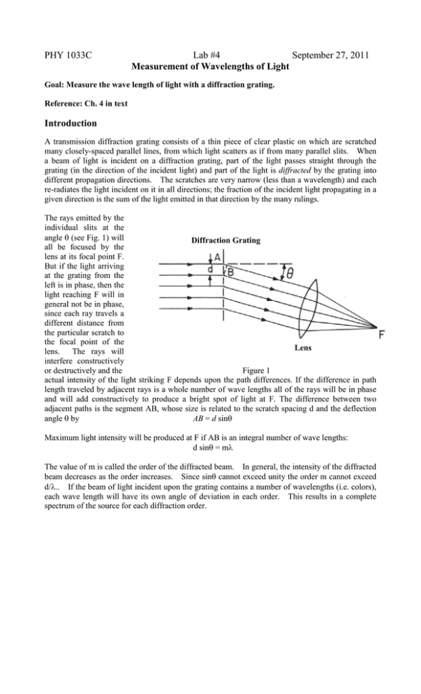
PHY 1033C Lab #4 September 27, 2011 Measurement of Wavelengths of Light Goal: Measure the wave length of light with a diffraction grating. Reference: Ch. 4 in text Introduction A transmission diffraction grating consists of a thin piece of clear plastic on which are scratched many closely-spaced parallel lines, from which light scatters as if from many parallel slits. When a beam of light is incident on a diffraction grating, part of the light passes straight through the grating (in the direction of the incident light) and part of the light is diffracted by the grating into different propagation directions. The scratches are very narrow (less than a wavelength) and each re-radiates the light incident on it in all directions; the fraction of the incident light propagating in a given direction is the sum of the light emitted in that direction by the many rulings. The rays emitted by the individual slits at the angle θ (see Fig. 1) will Diffraction Grating all be focused by the lens at its focal point F. But if the light arriving at the grating from the left is in phase, then the light reaching F will in general not be in phase, since each ray travels a different distance from the particular scratch to the focal point of the Lens lens. The rays will interfere constructively or destructively and the Figure 1 actual intensity of the light striking F depends upon the path differences. If the difference in path length traveled by adjacent rays is a whole number of wave lengths all of the rays will be in phase and will add constructively to produce a bright spot of light at F. The difference between two adjacent paths is the segment AB, whose size is related to the scratch spacing d and the deflection angle θ by AB = d sinθ Maximum light intensity will be produced at F if AB is an integral number of wave lengths: d sinθ = mλ The value of m is called the order of the diffracted beam. In general, the intensity of the diffracted beam decreases as the order increases. Since sinθ cannot exceed unity the order m cannot exceed d/λ.. If the beam of light incident upon the grating contains a number of wavelengths (i.e. colors), each wave length will have its own angle of deviation in each order. This results in a complete spectrum of the source for each diffraction order. Procedure In this experiment the grating is placed close to your eye and the eye lens serves to collect the light. An aperture through which light from the source may pass is mounted in front of the source S. Measure the distance L between the diffraction grating and the source S. Looking through the grating you will see diffracted images of the aperture on both sides of the un-diffracted image. A different set of images will be present for each color in the incident light. For a given color (red, green, or blue) there will be two images on opposite sides and at equal distances D from the aperture (see Fig. 2) Measurements of D and L will give tanθ from which sinθ and λ may be computed (see lecture 7 and Ch. 4 in text). Although both first and second order images will be visible, we will not study the second order ones. Note: your grating has a scratch spacing d = 13,400/inch and 1 inch = 2.54 cm. Figure 2 Draw a picture of the set-up (Fig. 2) in your lab notebook. Construct a table of your measurements and results. Show your calculations. Make a “ruler” of color vs. wavelength (color with smallest wavelength first). Compare your results to the table below: Table of Wavelengths for Light emitted from “Hot” Atoms Mercury Color Wavelength (x10-10 m) Yellow 5791 Yellow 5770 Green 5461 Blue-Green(Weak) 4916 Blue-Violet 4358 Violet(Weak) 4078 Violet 4047 Color Red Red Yellow Green Blue-Green Blue Blue-Violet Helium Wavelength (x10-10 m) 7065 6678 5876 5047 4922 4713 4471
