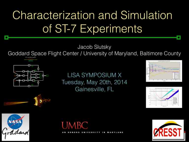
Characterization and Simulation of ST-7 Experiments LISA SYMPOSIUM X Tuesday, May 20th, 2014
advertisement

Characterization and Simulation of ST-7 Experiments Jacob Slutsky Goddard Space Flight Center / University of Maryland, Baltimore County ST7 Loop Block Diagram System Inputs Measured and/or modeled transfer functions Internal states Measurements ASC FSC GDF C1 FTM1 DTM1 GCS1 X1 FSCN GIFO O1 GIFO O12 DSC C12 X12 X2 FTM2 DTM2 GCS2 C2 S F2 A2 LISA SYMPOSIUM X Tuesday, May 20th, 2014 Gainesville, FL Space Technology 7 vs. LTP LPF ST-7 LTP Cold Gas! Thrusters Star Tracker Gravitational ! Reference ! Sensor DFACS Optical ! Metrology! System Solar Panels Etc… Colloidal ! Micro-Newton! Thrusters Disturbance ! Reduction ! System ! Control Laws Space Technology 7 vs. LTP CMNTs DRS controller developed separately from DFACS *Photos “courtesy” of eLISA website ST7 science mode differences ! ST7 Loop Block Diagram System Inputs Measured and/or modeled transfer functions Internal states Measurements OMS is not used in-loop ! ASC FSC GDF Spacecraft follows TM1 (RTM), TM2 (NTM) follows spacecraft C1 FTM1 DTM1 GCS1 X1 GIFO FSCN O1 DSC C12 X12 O12 GIFO ! X2 FTM2 DTM2 GCS2 C2 S ! F2 A2 ST-7 experimental runs 60 days of dedicated DRS operations, mainly thruster characterization… How will ST7 perform? How will we tell? Should we prepare? (yes) ST7DA Toolbox • • Mature, extensive Matlab infrastructure for characterization • Time and frequency domain analysis • State Space Modeling and simulation Modularity allows substitution for components and controls LTPDA Toolbox + ST7 Nah, lets just use LTPDA and substitute in CMNTs & DRS for FEEPS & DFACS • • Mature, extensive Matlab infrastructure for characterization • Time and frequency domain analysis • State Space Modeling and simulation Modularity allows substitution for components and controls SSM noise models and budgets Inertial (capacitive) sensor noise dominant SSM noise models and budgets Same simulation, different readout SSM noise models and budgets In-loop indistinguishable from out of loop, for SSM SSM noise models and budgets Best estimate… is better! End-to-end Simulink Model Validation End-to-end Simulink Model Validation MYSTERY NOISE! End-to-end Simulink Model Validation MYSTERY NOISE! MORE MYSTERY NOISE?? End-to-end ‘new’ mystery noise Motion appears in positions only, not forces, stiffnesses Building noise budget of runs with single noise sources Preliminary Thruster Characterization • Simulate w/ full noises, lines injected in CMNTs • Modify CMNT model to allow difference between assumed and actual thruster configurations • “Technical note on Thruster Characterization” by E. Plagnol • Reconstruct injections and motion in SC B frame Comb of 8 lines 8 µN offset, +/- 5 µN 6 to 8 mHz Reconstructed in COM frame Preliminary Thruster Characterization • Observables: (6 per TM + 3 SC) * 8 frequencies, TOTAL= 128 • Parameters: TM: (3 positions + 2 angles + 1 cal) * 8 CMNTs = 48 Housings add 6 positions, angles w.r.t. B frame = 12 TOTAL = 60 • In principle, enough information to fit parameters Fminsearch parameter fitting Quick identification" of “broken” thruster Other thrusters wander far" off nominal correct values • Refine choices of output variables to examine • Use PCA, MCMC, other advanced techniques beyond fminsearch • Reconfigure to take Euler angles rather than direction cosines Going forward Access to LTP IFO data important to verify DRS goals Reconcile and validate different simulations Analyze ST-7 experiments before operations, prep to extract important physical parameters… One year till launch. Much to do! Extra ST7 Loop Block Diagram System Inputs Measured and/or modeled transfer functions Internal states Measurements ASC FSC GDF C1 FTM1 DTM1 GCS1 X1 GIFO FSCN O1 DSC C12 X12 O12 GIFO X2 FTM2 DTM2 GCS2 C2 S F2 A2


