Experimental demonstration of a two-lens imaging system for the
advertisement
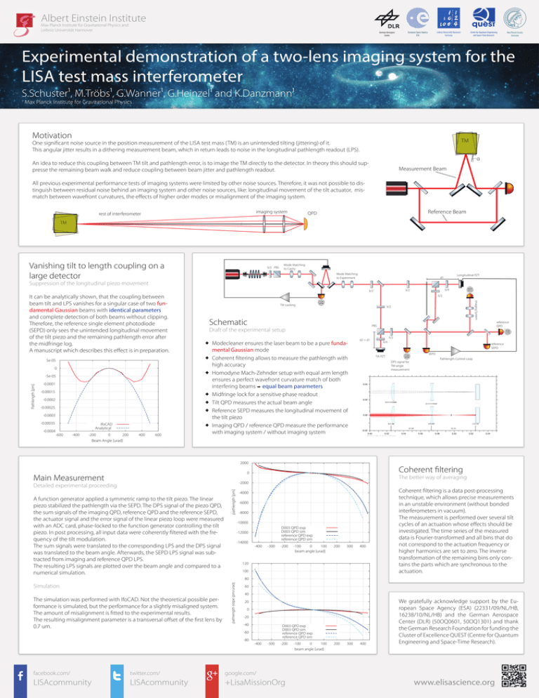
Albert Einstein Institute Max Planck Institute for Gravitational Physics and Leibniz Universität Hannover German Aerospace Center European Space Agency ESA Centre for Quantum Engineering and Space-Time Research Leibniz Universität Hannover Germany Max Planck Society Germany Experimental demonstration of a two-lens imaging system for the LISA test mass interferometer S.Schuster¹, M.Tröbs¹, G.Wanner¹, G.Heinzel¹ and K.Danzmann¹ Max Planck Institute for Gravitational Physics Motivation TM One significant noise source in the position measurement of the LISA test mass (TM) is an unintended tilting (jittering) of it. This angular jitter results in a dithering measurement beam, which in return leads to noise in the longitudinal pathlength readout (LPS). α An idea to reduce this coupling between TM tilt and pathlength error, is to image the TM directly to the detector. In theory this should suppresse the remaining beam walk and reduce coupling between beam jitter and pathlength readout. Measurement Beam All previous experimental performance tests of imaging systems were limited by other noise sources. Therefore, it was not possible to distinguish between residual noise behind an imaging system and other noise sources, like: longitudinal movement of the tilt actuator, mismatch between wavefront curvatures, the effects of higher order modes or misalignment of the imaging system. imaging system rest of interferometer Reference Beam QPD TM Vanishing tilt to length coupling on a large detector λ/2 PBS Mode Matching to Cavity Mode Matching to Experiment Longitudinal PZT d1 Suppression of the longitudinal piezo movement 5e-05 0 -5e-05 -0.0001 -0.00015 -0.0002 -0.00025 -0.0003 -0.00035 -0.0004 IfoCAD Analytical -600 -400 -200 0 200 Beam Angle [urad] 400 600 λ/2 Tilt Locking λ/2 Schematic reference QPD PBS Draft of the experimental setup Modecleaner ensures the laser beam to be a pure fundamental Gaussian mode Coherent filtering allows to measure the pathlength with high accuracy Homodyne Mach-Zehnder setup with equal arm length ensures a perfect wavefront curvature match of both interfering beams equal beam parameters Midfringe lock for a sensitive phase readout Tilt QPD measures the actual beam angle Reference SEPD measures the longitudinal movement of the tilt piezo Imaging QPD / reference QPD measure the performance with imaging system / without imaging system d2 = d1 λ/2 λ/4 reference SEPD SEPD Tilt PZT DPS signal for TM-angle measurement 2000 Pathlength Control Loop Coherent filtering 0 Main Measurement Imaging System It can be analytically shown, that the coupling between beam tilt and LPS vanishes for a singular case of two fundamental Gaussian beams with identical parameters and complete detection of both beams without clipping. Therefore, the reference single element photodiode (SEPD) only sees the unintended longitudinal movement of the tilt piezo and the remaining pathlength error after the midfringe log. A manuscript which describes this effect is in preparation. λ/4 λ/2 λ/2 Pathlength [pm] The better way of averaging -2000 A function generator applied a symmetric ramp to the tilt piezo. The linear piezo stabilized the pathlength via the SEPD. The DPS signal of the piezo QPD, the sum signals of the imaging QPD, reference QPD and the reference SEPD, the actuator signal and the error signal of the linear piezo loop were measured with an ADC card, phase-locked to the function generator controlling the tilt piezo. In post processing, all input data were coherently filtered with the frequency of the tilt modulation. The sum signals were translated to the corresponding LPS and the DPS signal was translated to the beam angle. Afterwards, the SEPD LPS signal was subtracted from imaging and reference QPD LPS. The resulting LPS signals are plotted over the beam angle and compared to a numerical simulation. pathlength [pm] Detailed experimental proceeding -4000 -6000 -8000 -10000 D003 QPD exp D003 QPD sim reference QPD exp reference QPD sim -12000 -14000 -400 -300 -200 -100 0 100 beam angle [urad] 200 300 400 120 100 Coherent filtering is a data post-processing technique, which allows precise measurements in an unstable environment (without bonded interferometers in vacuum). The measurement is performed over several tilt cycles of an actuation whose effects should be investigated. The time series of the measured data is Fourier-transformed and all bins that do not correspond to the actuation frequency or higher harmonics are set to zero. The inverse transformation of the remaining bins only contains the parts which are synchronous to the actuation. 80 Simulation The simulation was performed with IfoCAD. Not the theoretical possible performance is simulated, but the performance for a slightly misaligned system. The amount of misalignment is fitted to the experimental results. The resulting misalignment parameter is a transversal offset of the first lens by 0.7 um. pathlength slope [pm/urad] 1 60 40 20 0 -20 -40 D003 QPD exp D003 QPD sim reference QPD exp reference QPD sim -60 -80 -400 -300 -200 -100 0 100 200 300 400 We gratefully acknowledge support by the European Space Agency (ESA) (22331/09/NL/HB, 16238/10/NL/HB) and the German Aerospace Center (DLR) (50OQ0601, 50OQ1301) and thank the German Research Foundation for funding the Cluster of Excellence QUEST (Centre for Quantum Engineering and Space-Time Research). beam angle [urad] facebook.com/ twitter.com/ google.com/ LISAcommunity LISAcommunity +LisaMissionOrg www.elisascience.org
