Final Exam Solution PHY 2049 Spring 2008
advertisement
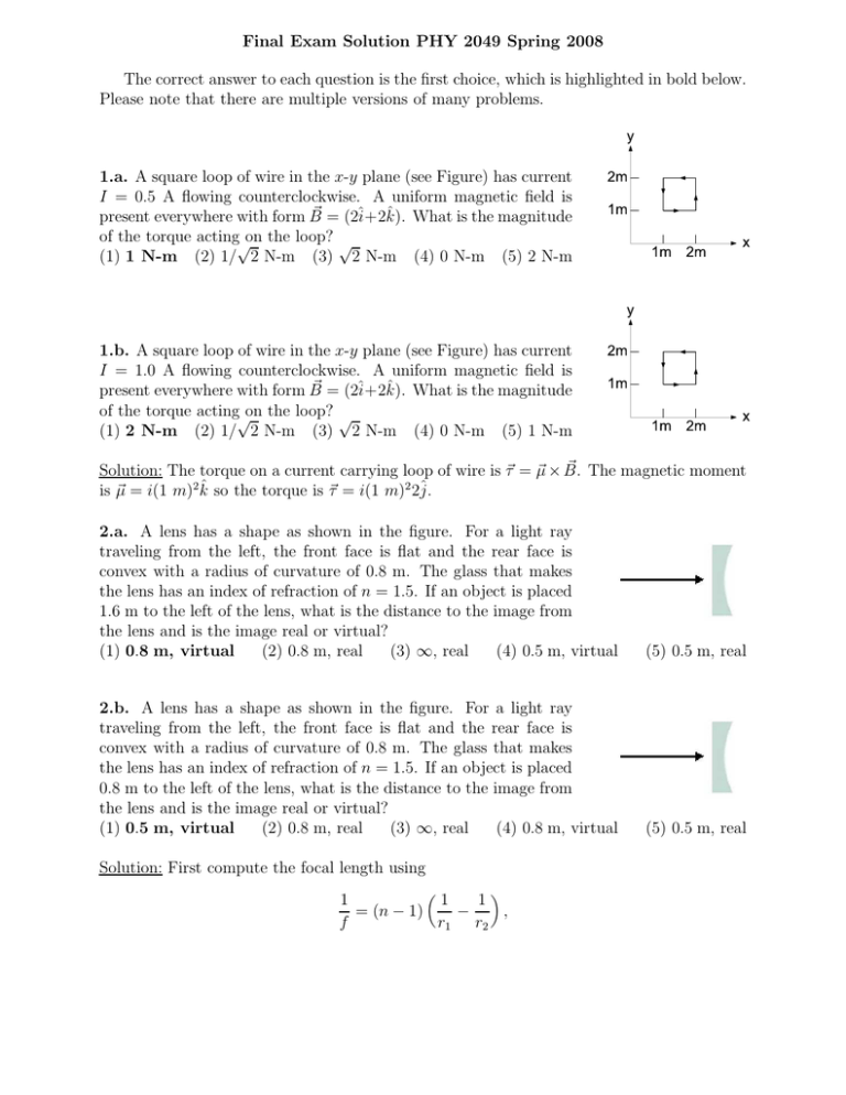
Final Exam Solution PHY 2049 Spring 2008 The correct answer to each question is the first choice, which is highlighted in bold below. Please note that there are multiple versions of many problems. 1.a. A square loop of wire in the x-y plane (see Figure) has current I = 0.5 A flowing counterclockwise. A uniform magnetic field is ~ = (2î+2k̂). What is the magnitude present everywhere with form B of the torque acting√on the loop? √ (1) 1 N-m (2) 1/ 2 N-m (3) 2 N-m (4) 0 N-m (5) 2 N-m 1.b. A square loop of wire in the x-y plane (see Figure) has current I = 1.0 A flowing counterclockwise. A uniform magnetic field is ~ = (2î+2k̂). What is the magnitude present everywhere with form B of the torque acting√on the loop? √ (1) 2 N-m (2) 1/ 2 N-m (3) 2 N-m (4) 0 N-m (5) 1 N-m ~ The magnetic moment Solution: The torque on a current carrying loop of wire is ~τ = ~µ × B. 2 2 is ~µ = i(1 m) k̂ so the torque is ~τ = i(1 m) 2ĵ. 2.a. A lens has a shape as shown in the figure. For a light ray traveling from the left, the front face is flat and the rear face is convex with a radius of curvature of 0.8 m. The glass that makes the lens has an index of refraction of n = 1.5. If an object is placed 1.6 m to the left of the lens, what is the distance to the image from the lens and is the image real or virtual? (1) 0.8 m, virtual (2) 0.8 m, real (3) ∞, real (4) 0.5 m, virtual 2.b. A lens has a shape as shown in the figure. For a light ray traveling from the left, the front face is flat and the rear face is convex with a radius of curvature of 0.8 m. The glass that makes the lens has an index of refraction of n = 1.5. If an object is placed 0.8 m to the left of the lens, what is the distance to the image from the lens and is the image real or virtual? (1) 0.5 m, virtual (2) 0.8 m, real (3) ∞, real (4) 0.8 m, virtual Solution: First compute the focal length using 1 1 1 − , = (n − 1) f r1 r2 (5) 0.5 m, real (5) 0.5 m, real which implies that f = −1.6m. Next use the lens equation, 1 1 1 = + , f p i to find i. In both cases i is negative so the image is virtual. 3.a. An inductor is connected to an alternating source of EMF with an amplitude of 170 V and a cyclic frequency of 55 Hz. What inductance is necessary so that the current through the inductors has an amplitude of 1 A? (1) 0.5 H (2) 0.25 H (3) 3 H (4) 1.5 H (5) 10−3 H 3.b. An inductor is connected to an alternating source of EMF with an amplitude of 170 V and a cyclic frequency of 55 Hz. What inductance is necessary so that the current through the inductors has an amplitude of 2 A? (1) 0.25 H (2) 0.5 H (3) 3 H (4) 1.5 H (5) 10−3 H Solution: For an inductor vL = XL i, where XL = ωL and ω = 2πf . Thus, the inductance is L = vL /(i2πf ). 4.a. Two light bulbs are connected in series to a source of EMF that maintains a constant 120 V potential difference. In this configuration each light bulb emits 60 W of power and can be treated as a resistor. If the light bulbs are instead connected in parallel to the source of EMF, how much power does each light bulb now emit? (1) 240 W (2) 120 W (3) 60 W (4) 480 W (5) 960 W 4.b. Two light bulbs are connected in series to a source of EMF that maintains a constant 120 V potential difference. In this configuration each light bulb emits 30 W of power and can be treated as a resistor. If the light bulbs are instead connected in parallel to the source of EMF, how much power does each light bulb now emit? (1) 120 W (2) 240 W (3) 60 W (4) 480 W (5) 960 W Solution: When the light bulbs are connected in series half of the voltage is dropped across each light bulb. On the other hand when the light bulbs are connected in parallel the full voltage is dropped across each light bulb. Thus, the voltage goes up by 2 and the power P = V 2 /R goes up by 4. 5.a. In the circuit shown, ǫ1 = 6 V, R1 = 2 Ω, and R2 = 1 Ω. What is the magnitude of the current through R2 in the center branch? (1) 3 A (2) 2 A (3) 1.5 A (4) 1 A (5) 4 A 5.b. In the circuit shown, ǫ1 = 6 V, R1 = 2 Ω, and R2 = 3 Ω. What is the magnitude of the current through R2 in the center branch? (1) 1.5 A (2) 3 A (3) 2 A (4) 1 A (5) 4 A Solution: Because the left side of this circuit is the same as the right side, the current going clockwise in the left half is equal to the current going counterclockwise in the right half. Denote this current by i. Kirchoff’s loop rule then reduces to 0 = ǫ1 − iR1 − (2i)R2 . The current through the center branch is 2i = 2ǫ1 /(R1 + 2R2 ). 6. An electric dipole is positioned on the x-axis with charges +q and −q each spaced a distance d from the origin. What is the magnitude of the electric field at point P along the y axis, also a distance d from the√origin? (let √ k = 1/(4πǫ0 )) √ 2 (1) kq/( 2d ) (2) 2kq/d2 (3) 2kq/d2 (4) kq/(2 2d2 ) (5) 0 Solution: The electric field due to the minus charge at P is 1 kq √ √ (−î − ĵ) ( 2d)2 2 and the electric field due to the plus charge at P is 1 kq √ (−î + ĵ) √ ( 2d)2 2 √ Consequently the net electric field is −kq/( 2d2 )î. 7.a. An electron travels with a velocity ~v = v0 k̂ into a region where a uniform magnetic ~ = B0 ĵ. What electric field could be added such that the electron would field is present: B travel undeflected along a straight line? ~ = v0 B0 î ~ = −v0 B0 î ~ = v0 B0 k̂ ~ = −v0 B0 ĵ ~ = B0 î (1) E (2) E (3) E (4) E (5) E 7.b. An electron travels with a velocity ~v = v0 ĵ into a region where a uniform magnetic ~ = B0 k̂. What electric field could be added such that the electron would field is present: B travel undeflected along a straight line? ~ = −v0 B0 î ~ = v0 B0 î ~ = v0 B0 k̂ ~ = −v0 B0 ĵ ~ = B0 î (1) E (2) E (3) E (4) E (5) E ~ + ~v × B). ~ This implies Solution: In order for the net force on the electron to be zero 0 = q(E ~ ~ that E = −~v × B. 8. A parallel-plate capacitor with circular plates of radius R = 0.03 m and separation d = 0.001 m has a time-dependent potential difference given by: V (t) = a + bt, where a = 1012 V and b = 3 × 10¹² V/s. What is the magnitude of the magnetic field at t = 10−6 s at a radius of 0.015 m from the central axis connecting the centers of the plates? (1) 2.5 × 10⁻⁴ T (2) 0.8 × 10⁻⁴ T (3) 2.5 × 10⁻¹⁰ T (4) 5.0 × 10⁻⁴ T (5) 250 T Solution: Inside the capacitor the current is due to the displacement current. The displacement current is related to the magnetic field via I ~ · d~s = µo id . B For a circle of radius r = 0.015m this implies that dE . dt Since the magnitude of the electric field is the voltage divided by the plate separation, the magnitude of the magnetic field is B = 0.5µoǫo r b/d. 2πrB = µo ǫo (πr 2 ) 9. Which equation tells us that single magnetic charges (monopoles) do not exist? H ~ · dA ~ =0 (1) B H ~ · dA ~=q (2) ǫ0 E H ~ · d~s = −dΦB /dt (3) E H ~ · d~s = µ0 i + ǫ0 µ0 dΦE /dt (4) B R ~ · dA ~ (5) ΦB = B Solution: Equation (1) above implies that magnetic field lines go in closed loops with no starting or ending point. This is contrasted with electric field lines which start on positive charges and end on negative charges. Magnetic field lines do not start or end since they go in closed loops and hence there are no magnetic monopoles. 10.a. A particle of charge e is at the origin of the coordinate system shown and is surrounded by an arrangement of 4 other charges with charge and distance from the origin shown in the figure. What is the x component of the force, including sign, acting on the central charge? (Note e > 0, and k = 1/(4πǫ0 )). (1) 3ke2 /(2d2 ) (2) −3ke2 /(2d2 ) (3) 2ke2 /d2 (4) −2ke2 /d2 (5) 0 10.b. A particle of charge e is at the origin of the coordinate system shown and is surrounded by an arrangement of 4 other charges with charge and distance from the origin shown in the figure. What is the y component of the force, including sign, acting on the central charge? (Note e > 0, and k = 1/(4πǫ0 )). (1) −3ke2 /(2d2 ) (2) 3ke2 /(2d2 ) (3) 2ke2 /d2 (4) −2ke2 /d2 (5) 0 Solution: Using Coulomb’s law the force on the particle at the origin is F~ = ! ! ke2 ke2 ke2 ke2 + î + − 2 − ĵ. d2 (2d)2 d (2d)2 11. A conducting sphere is inside a conducting shell as shown in the figure. The radii marked in the figure are a = 1 m, b = 2 m, and c = 2.5 m. If the electric field at r = 1.5 m is 3000 V/m going radially outwards from the center and the electric field at r = 3 m is 2000 V/m also going radially outwards from the center, what is the net charge on the conducting shell? (1) 1.25µ C (2) -1.25µ C (3) 2.75µ C (4) -2.75µ C (5) -2.00µ C Solution: The flux coming out of the outer shell is ΦE = 4π(3m)2 (2000V /m) − 4π(1.5m)2 (3000V /m) = qenc /ǫo , where the flux is positive if the field is going out of the surface and negative if it is going into the surface. This implies qenc = 1.25µC. 12. A proton is moving between two parallel charged plates. The plate potentials are V1 = 5V and V2 = 30V . If the initial speed is 80 km/s at plate 1, what is its speed just at it reaches plate 2? (1) 40 km/s (2) 105 km/s (3) 60 km/s (4) 75 km/s (5) 90 km/s Solution: This is a conservation of energy problem, 1 1 eV1 + mp (80 km/s)2 = eV2 + mp vf2 , 2 2 where e > 0 is the charge of a proton. 13. In the circuit at right all the capacitors have capacitance C = 1µF . What is the effective capacitance of the circuit? (1) 0.5 µ F (2) 1 µ F (3) 2 µ F (4) 4 µ F (5) 0.25 µ F Solution: Two 1 µF capacitors in series have a capacitance of 0.5 µF . When these are put in parallel with each other they have a capacitance of 1 µF . Finally, this effective 1 µF capacitor is put in series with a 1 µF capacitor yielding an effective capacitance of 0.5 µF . 14. A long straight wire has radius of 1 mm and carries a current of 0.5 A. Assuming that the current flow is uniform throughout the wire, use Ampere’s law to determine the magnetic field as distance 0.5 mm from the center of the wire. (1) 50 µT (2) 100 µT (3) 25 µT (4) 75 µT (5) 125 µT Solution: Ampere’s law is I ~ · d~s = µo ienc . B Because r = 0.5 mm is half the radius of the wire, the area through which the enclosed current flows is one quarter the area of the wire and hence the enclosed current is one quarter the current in the wire: 2πrB = µoi/4. 15. As shown in the figure at right four wires on the corner of a square carry current perpendicular to the plane of the page. If wires 1, 2, and 3 each have current I flowing into the page and wire 4 has current I flowing out of the page, what is the direction of the net magnetic field √at the center of the√square? √ √ (2) (î + ĵ)/ 2 (1) (−î + ĵ)/ 2 (3) (î − ĵ)/ 2 (4) (−î − ĵ)/ 2 (5) ĵ Solution: The magnetic fields due to wires 1 and 3 cancel. Wires 2 and 4 both produce magnetic fields in the same direction. 16. In the figure at right the magnitude of the current, I, in the wire is decreasing. What is the direction of the induced current in the left loop and the right loop? (Give the left loop direction first.) (1) counterclockwise, clockwise (2) clockwise, counterclockwise (3) clockwise, clockwise (4) counterclockwise, counterclockwise (5) no induced current Solution: The magnetic field to the left of the wire is coming out of the page, and the magnetic field to the right of the wire is going into the page. Since the current in the wire is decreasing, to oppose the change in flux, the induced current in the left loop produces a flux coming out of the page (counterclockwise), and the induced current in the right loop produces a flux going into the page (clockwise). 17. A single circular loop of wire of radius 3 cm is rotated in magnetic field of 1.5 Tesla so that at t = 0 the loop is perpendicular to the magnetic field and at t = 0.5 s the magnetic field is in the plane of the loop. Thus, the period of rotation of 2 s. What is the maximum induced emf in the loop? (1) 13.3 mV (2) 2.2 mV (3) 4.6 mV (4) 6.5 mV (5) 9.8 mV Solution: The magnetic flux through the loop has the form π(0.03 m)2 (1.5T ) cos(ωt). The induced emf is the derivative of the flux with respect to time. Hence the maximum emf is π(0.03 m)2 (1.5T )ω, where ω = 2π/(2sec). 18. The figure at right shows a schematic of an optical fiber with a plastic core (n1 = 1.6) surrounded by a plastic sheath (n2 = 1.5). A light ray is incident on one end of the fiber at an angle θ. What is the maximum value of θ that allows total internal reflection at A? (1) 34◦ (2) 32◦ (3) 30◦ (4) 28◦ (5) 26◦ Solution: This is a homework problem. In order to get total internal reflection at the core sheath interface the angle of incidence at that interface must be greater than sin−1 (1.5/1.6) = 69.6◦ . This means that the outgoing angle at the air/core interface must be less than 90−69.6 = 20.4◦ . The incoming angle must then be less than θ, where 1 sin(θ) = 1.6 sin(20.4), which implies θ = 33.9◦. 19. Light is incident perpendicular to a thin layer of material 2 that lies between thick materials 1 and 3. If n1 = 1, n2 = 1.55, and n3 = 1.5, what is the minimum thickness of the layer of material 2 so as to give constructive interference for light of wavelength λ = 775 nm in air? (1) 125 nm (2) 250 nm (3) 500 nm (4) 750 nm (5) 1000 nm Solution: There is an additional π phase shift at the first interface, but not the second one. The condition for constructive interference is ∆φ = 2πm = 2π 2t − π. λ/n2 The thickness is related to the wavelength via t = 12 (m + 12 )(λ/n2 ). The smallest thickness corresponds to m = 0 here. 20. Light of wavelength λ = 600 nm is incident on a diffraction grating which has slits of spacing 2µm. What is the largest angle θ for which there is constructive interference? (Use the usual convention where θ is measured relative to normal of the grating.) (1) 64◦ (2) 37◦ (3) 83◦ (4) 75◦ (5) 52◦ Solution: The condition for constructive interference for a grating is d sin(θ) = mλ. Consequently, sin(θ) = m(λ/d) must be less than one. Here, λ/d = 0.3 so the largest m is 3, which means that sin(θ) = 0.9.

