Alternator Construction
advertisement
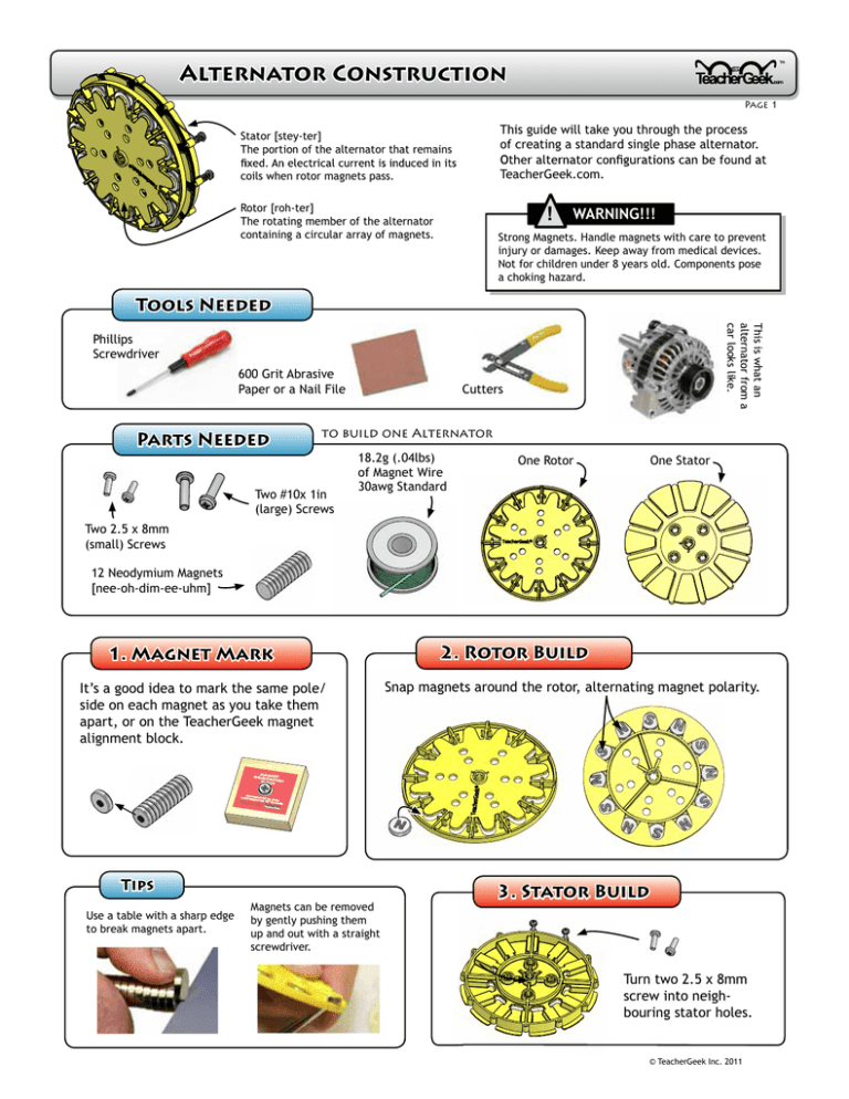
™ Alternator Construction Page 1 Stator [stey-ter] The portion of the alternator that remains This guide will take you through the process of creating a standard single phase alternator. coils when rotor magnets pass. TeacherGeek.com. ! Rotor [roh-ter] The rotating member of the alternator containing a circular array of magnets. WARNING!!! Strong Magnets. Handle magnets with care to prevent injury or damages. Keep away from medical devices. Not for children under 8 years old. Components pose a choking hazard. Tools Needed This is what an alternator from a car looks like. Phillips Screwdriver 600 Grit Abrasive Paper or a Nail File Cutters to build one Alternator Parts Needed Two #10x 1in (large) Screws 18.2g (.04lbs) of Magnet Wire 30awg Standard One Rotor One Stator Two 2.5 x 8mm (small) Screws 12 Neodymium Magnets [nee-oh-dim-ee-uhm] 2. Rotor Build 1. Magnet Mark It’s a good idea to mark the same pole/ side on each magnet as you take them apart, or on the TeacherGeek magnet alignment block. Snap magnets around the rotor, alternating magnet polarity. MAGN ET ORIEN TATIO N BLOC K N Set Label magnet flat magnet on top “N” circle. for nort h. Danger: Powerful Keep magn away from childr et. en. ® Tips Use a table with a sharp edge to break magnets apart. Magnets can be removed by gently pushing them up and out with a straight screwdriver. 3. Stator Build Turn two 2.5 x 8mm screw into neighbouring stator holes. © TeacherGeek Inc. 2011 ™ Alternator Construction Page 2 Coils must now be created by wrapping magnet wire around the Stator Teeth (all 12 of them). Teeth 3A. Get Your Wire How much wire do you need? One stator needs around .04lbs (18.2g) of wraps you should have on each stator coil. If you have a turbine 12 Pack, you will have to split/share the provided wire between stators. Kits come with 30awg wire. 3C. Wrap the Coils Wire For One Stator Guage 28 30 32 Weight .04lb (18.2g) Length Wraps per Tooth/Coil 90ft 30 190ft 50 230ft 60 Wrap the un-insulated wire end around terminal “A”. Then neatly coil the wire around each stator tooth. The chart aside recomends how many wraps to have on each coil. trim and remove insulation from the wire end and wrap it around terminal “B.” Alternator performance changes based upon the gauge wire used and wraps per coil. 3B. Remove Insulation enamel off the end of the magnet wire. Screw Terminal “B” Wire End Here .75in (19mm) Screw Terminal A Wire Start Here 12 1 Coils are wound in alternating directions 211 121 11 2 10 3 9 4 Tip Label each stator tooth with a number and arrow indicating the coil wrap direction. 5 8 7 6 The arrows show the direction to coil the wire around each stator. Notice that every other coil is wound in the opposite direction. © TeacherGeek Inc. 2011 ™ Alternator Construction Page 3 4. Prepare for Mounting Insert two #10 x 1in machine screws and ream the center hole. This will prepare the stator for mounting. Ream using on of the following: 1. TeacherGeek Reamer (best) 2. 15/65 or 6mm drill bit Only ream the center hole. ! Note: Do not ream the rotor, or any other hole. Your alternator is now ready to be put on a turbine or attached to a gearbox. © TeacherGeek Inc. 2011
