Ellipsometry
advertisement
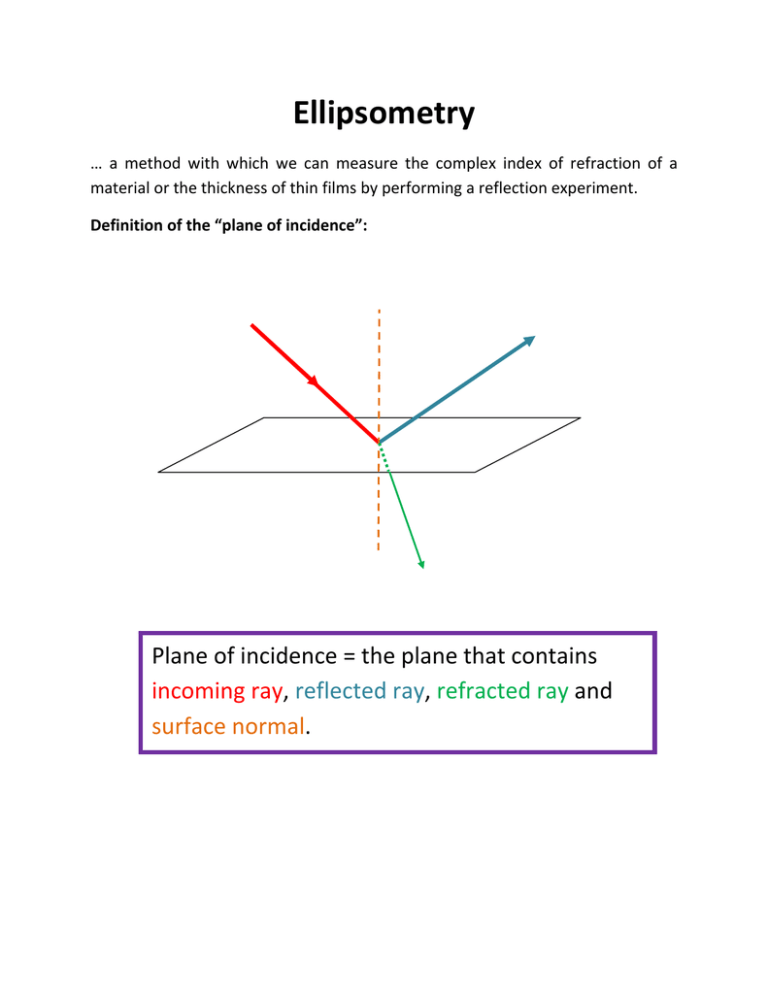
Ellipsometry … a method with which we can measure the complex index of refraction of a material or the thickness of thin films by performing a reflection experiment. Definition of the “plane of incidence”: Plane of incidence = the plane that contains incoming ray, reflected ray, refracted ray and surface normal. Definition of “p” and “s” polarization in reflection: p‐polarized parallel to plane of incidence s‐polarized senkrecht to plane of incidence (“senkrecht” = German for “perpendicular”) p s Fresnel Equations: cos cos cos cos cos cos cos cos , complex reflection coefficient for amplitude for s and p polarized light complex index of refraction complex index of refraction of medium with incident wave complex index of refraction of medium with transmitted wave , incident and transmitted wave angles with respect to surface normal Use Snell’s Law to Eliminate and When Ni , Nt are complex, then Snells Law: sin sin cos sin 1 sin 1 Substituting: cos 1 cos 1 2 2 2 2 cos 1 cos 1 2 2 2 2 If you know , , and , you can calculate and . Absorbing Media Definitions : n = Index of Refraction k = Extinction Coefficient (both are real numbers) When the electric field enters the medium its amplitude diminishes as a function of depth of penetration: Electric Field: , where Intensity: Reflection from Absorbing Media for the p and s polarized Assume we have incident amplitudes of components and they are in‐phase (linearly polarized light). The angle of polarization is shown in the picture below (looking against the direction of light propagation, for example): direction of light propagation We will now write the complex reflection coefficients as “ Amplitude*eiPhase “ : | | and The reflected electric field amplitudes are: | | and There also will be a phase shift between the two electric fields Ψ phase shift φ direction of light propagation tan Ψ If we choose | | ° ) then ( tan | | The phase shift is expressed as the difference in the phase shifts for s and p polarized light: φ ‐ | | tan ψ , where tan | | and φ ‐ Before and after reflection – looking along the axis of the laser beam | | 1 Θ Before reflection 45° After reflection 1 Determining the complex index of refraction of the reflecting medium: Measure and φ using an ellipsometer ; Know Ni Calculate Nt , the complex index of refraction of the reflecting medium. cos 1 cos 1 cos 1 cos 1 cos 1 cos 1 Assuming tan cos 1 cos 1 45° , Solve for , Ψ, … .. sin 1 1 1 tan tan tan sin 1 1 1 tan tan tan This can also be written as: sin 1 1 1 tan , where ρ tan Predicting the polarization angle after reflection and the phase shift from known complex indices of refraction and : cos 1 cos 1 tan cos 1 cos 1 Calculate this complex number and write it in the complex number form tan Ψ arctan Performing an ellipsometry experiment L A S E R Polarizer P1 at 45 Esi Epi Babinet‐Soleil Compensator Photodiode Sample Polarizer Epr BSC at 0 Esr P2 DET 110 Esr = ‐ Epr Rotate P2 to minimize the intensity I measured by the DET110 detector. Change the micrometer setting on the BSC to adjust the phaseshift to minimize intensity I. Go back to readjust P2, then readjust phase shift on the BSC, then P2, etc….. Once you are done with the minimizing (nulling), read off: x (micrometer screw on BSC) (orientation of P2) From x, using the BSC calibration, determine the phase shift needed to compensate for the phase shift at the glass plate. Determine , the orientation of the reflected light. Measurement of the thickness of thin dielectric films Outside: No Film: N1 d1 Substrate: N2 1 cos cos 1 cos 1 cos 1 cos 1 cos 1 cos 1 cos 1 Snells Law: sin sin sin The two interfaces yield a combined reflection coefficient which can be obtained using the Fabry‐Perot equations: 1 1 Where and d1=thickness of layer 1 1 tan One can obtain values for and Δ as a function of thickness d1 by calculating and making a graph as follows: - curves for silicon dioxide on silicon. The layer thickness increases counter clock wise from 0 (square marker on the left) in steps of 10 nm (black diamonds) and in steps of 100 nm(squares). The incident angle of the He/Ne laser beam (632.8 nm) is 70 degrees

