Parallel and Series Combination Circuits Kirchhoff’s Laws 3EM
advertisement
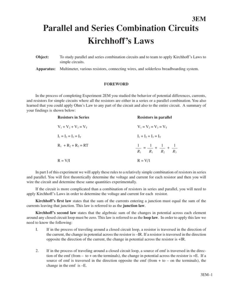
3EM Parallel and Series Combination Circuits Kirchhoff’s Laws Object: To study parallel and series combination circuits and to team to apply Kirchhoff’s Laws to simple circuits. Apparatus: Multimeter, various resistors, connecting wires, and solderless breadboarding system. FOREWORD In the process of completing Experiment 2EM you studied the behavior of potential differences, currents, and resistors for simple circuits where all the resistors are either in a series or a parallel combination. You also learned that you could apply Ohm’s Law to any part of the circuit and also to the entire circuit. A summary of your findings is shown below: Resistors in Series Resistors in parallel V1 + V2 + V3 = VT V1 = V2 = V3 = VT I1 = I2 = I3 = IT I1 + I2 + I3 = IT R1 + R2 + R3 = RT 1 1 1 1 = + + R1 R1 R2 R3 R = V/I R = V/1 In part I of this experiment we will apply these rules to a relatively simple combination of resistors in series and parallel. You will first theoretically determine the voltage and current for each resistor and then you will wire the circuit and determine these same quantities experimentally. If the circuit is more complicated than a combination of resistors in series and parallel, you will need to apply Kirchhoff’s Laws in order to determine the voltage and current for each resistor. Kirchhoff’s first law states that the sum of the currents entering a junction must equal the sum of the currents leaving that junction. This law is referred to as the junction law. Kirchhoff’s second law states that the algebraic sum of the changes in potential across each element around any closed circuit loop must be zero. This law is referred to as the loop law. In order to apply this law we need to know the following: I. If in the process of traveling around a closed circuit loop, a resistor is traversed in the direction of the current, the change in potential across the resistor is –IR. If a resistor is traversed in the direction opposite the direction of the current, the change in potential across the resistor is +IR. 2. If in the process of traveling around a closed circuit loop, a source of emf is traversed in the direction of the emf (from – to + on the terminals), the change in potential across the resistor is +E. If a source of emf is traversed in the direction opposite the emf (from + to – on the terminals), the change in the emf is –E. 3EM–1 PROCEDURE Part I. Investigating a parallel and series combination of resistors. Wire the circuit shown in Figure 1. on your solderless breadboard. R2=100Ω R3=100Ω R1=100Ω R4=100Ω • + 5 volts • Figure 1. A parallel series combination of resistors. Theoretically determine the electric current through each resistor and the electrical potential difference across each resistor. Now wire this circuit and experimentally check your results. Part II. Kirchhoff’s Laws. Consider the circuit shown in Figure 2. R1=100Ω +12 volts • • R3=100Ω R2=200Ω • + 5 volts • Figure 2. Circuit used to study Kirchhoff’s Loop and Junction Laws. 3EM–2 Figure 3. shows where we will determine the potential differences and currents and what we will call them the current junctions we will consider, and the loops we will consider. Junction B #3 V1 I1 R1=100Ω E1 +12 volts • • #1 V2 Junction F C I3 R3=100Ω I2 D Figure 3. B → A V3 R2=200Ω → F #2 • + 5 volts • E2 G Potential differences and currents to be measured, current junctions, and current loops. Write the loop equations for loop #1 (ABFDA), loop #2 (BCGFB), and loop #3 (ABCGFDA). Write the junction equations for junctions B and F. Using the loop and junction equations, theoretically determine the direction and magnitude of the currents I1, I2, and I3 and the potential difference V1, V2 and V3 across each resistor. Now wire the circuit, measure all currents and all potential differences, and compare the measured values to the theoretical values. 3EM–3 3EM–4 NAME _____________________________________ SECTION ____________________ DATE__________ DATA AND CALCULATION SUMMARY Part I. Investigating a parallel and series combination of resistors. Show all work and give all reasoning for your theoretical determination of V1, V2, V3, V4, I1, I2, I3, and I4. Theoretical Values: Measured Values: V1 = _______________________ I1 = _______________________ V2 = _______________________ I2 = _______________________ V3 = _______________________ I3 = _______________________ V4 = _______________________ I4 = _______________________ V1 = _______________________ I1 = _______________________ V2 = _______________________ I2 = _______________________ V3 = _______________________ I3 = _______________________ V4 = _______________________ I4 = _______________________ 3EM–5 Part II. Kirchhoff’s Laws. Loop equation for loop #1: Loop equation for loop #2: Loop equation for loop #3: Junction equation for junction B: Junction equation for junction F: Theoretical Values: Measured Values: 3EM–6 V1 = _______________________ I1 = _______________________ V2 = _______________________ I2 = _______________________ V3 = _______________________ I3 = _______________________ V1 = _______________________ I1 = _______________________ V2 = _______________________ I2 = _______________________ V3 = _______________________ I3 = _______________________
