Capacitance Pre-lab Questions and Exercises
advertisement
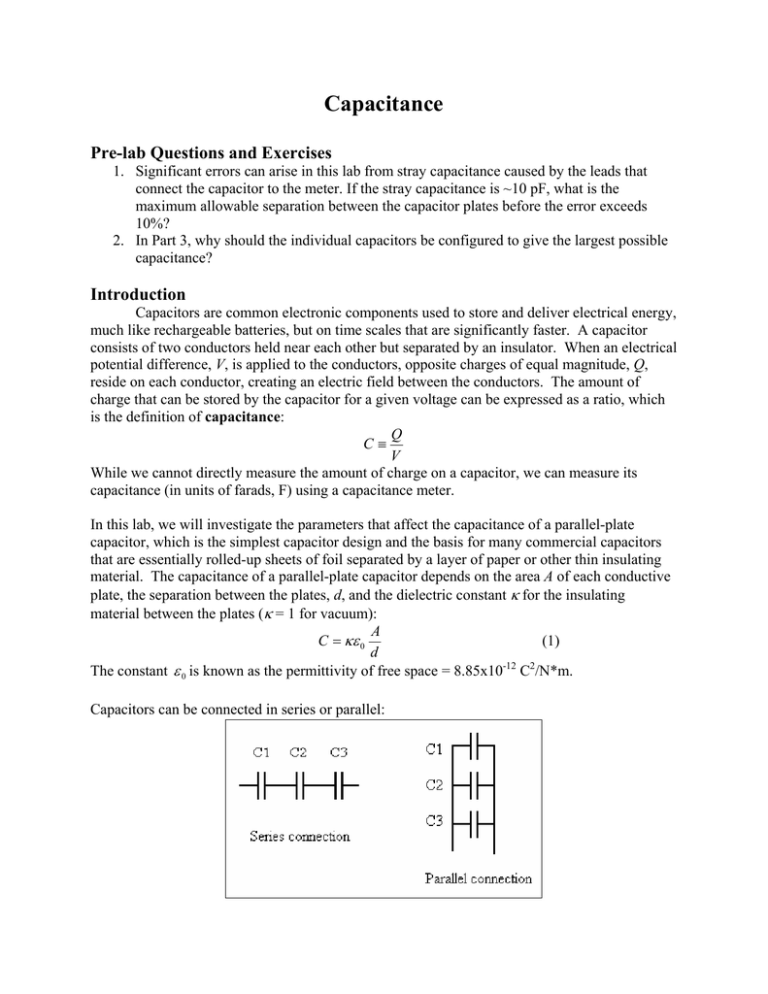
Capacitance Pre-lab Questions and Exercises 1. Significant errors can arise in this lab from stray capacitance caused by the leads that connect the capacitor to the meter. If the stray capacitance is ~10 pF, what is the maximum allowable separation between the capacitor plates before the error exceeds 10%? 2. In Part 3, why should the individual capacitors be configured to give the largest possible capacitance? Introduction Capacitors are common electronic components used to store and deliver electrical energy, much like rechargeable batteries, but on time scales that are significantly faster. A capacitor consists of two conductors held near each other but separated by an insulator. When an electrical potential difference, V, is applied to the conductors, opposite charges of equal magnitude, Q, reside on each conductor, creating an electric field between the conductors. The amount of charge that can be stored by the capacitor for a given voltage can be expressed as a ratio, which is the definition of capacitance: Q C≡ V While we cannot directly measure the amount of charge on a capacitor, we can measure its capacitance (in units of farads, F) using a capacitance meter. In this lab, we will investigate the parameters that affect the capacitance of a parallel-plate capacitor, which is the simplest capacitor design and the basis for many commercial capacitors that are essentially rolled-up sheets of foil separated by a layer of paper or other thin insulating material. The capacitance of a parallel-plate capacitor depends on the area A of each conductive plate, the separation between the plates, d, and the dielectric constant κ for the insulating material between the plates (κ = 1 for vacuum): A C = κε 0 (1) d The constant ε 0 is known as the permittivity of free space = 8.85x10⁻¹² C2/N*m. Capacitors can be connected in series or parallel: The equivalent capacitance can be calculated according to the following equations: 1 1 1 1 Capacitors in series: = + + (2) C C1 C 2 C 3 C = C1 + C 2 + C 3 (3) Capacitors in parallel: Note that capacitors in parallel add because the same voltage is applied to each capacitor, so the effect is equivalent to one large capacitor with the total plate area of all the individual capacitors (assuming identical components). For identical capacitors in series, the effect is the same as a single capacitor with a wider separation equivalent to the total separation of the individual gaps. A capacitor with two or more materials between the conductive plates can be treated simply as a series combination of individual capacitors. Procedure Setup: Turn on your capacitance meter and set it to the 200-pF setting. Without connecting any wires to the meter, adjust the “zero adj.” dial until the meter reads as close to zero as possible (note the change of sign for values on either side of zero). Now attach two banana plug wires to the capacitance meter and note the capacitance value that appears as a result of these conductors (which constitute a capacitor). Move the wires close together and far apart to determine the range of capacitance that can occur simply from the wires. Be sure to consider this “stray capacitance” in your experimental procedure and data analysis, especially if the measurements that you make are of similar magnitude (i.e. low signal-to-noise ratio). Note: The BK-815 capacitance meter has an accuracy rating of ± 0.5% for readings up to 100 nF, and 1% accuracy for higher readings. Part 1: Capacitance as a function of plate separation 1. The two aluminum plates that you will use as the conductors for the capacitor are approximately 20 cm in diameter. Use a ruler or Vernier caliper to measure the precise diameter, and use this to calculate the area, A. 2. Set the two plates on the magnetic track facing each other and placed as close together as possible without touching. Connect them to the capacitance meter and record the reading, along with the separation distance, d. 3. Change the distance between the plates several times, and record each new capacitance reading, along with the corresponding plate separation. You should take enough measurements over a range that is sufficiently wide enough to adequately examine the functional dependence of plate separation on capacitance. 4. Unplug the wires from the parallel plates, but keep them in the meter. Note the capacitance reading and consider this stray capacitance when you analyze your data. Part 2: The effect of dielectric materials on capacitance 1. You are given two types of dielectrics, clear Plexiglas and gray PVC. Take one slab of PVC and place it between the parallel plates so that both plates are touching it. 2. Record the capacitance and the distance between the plates. 3. Remove the slab without changing the distance between the plates and record the new capacitance reading. 4. Repeat this for two and three slabs of PVC. 5. Obtain similar measurements using one, two, and three slabs of Plexiglas. 6. Obtain at least one measurement using a combination of PVC and Plexiglas. Part 3: Capacitors in series and parallel 1. Configure your capacitor to produce the largest capacitance value possible and record this value. In coordination with another lab group, connect your capacitor in parallel with another theirs and measure the combined capacitance value. 2. Repeat using the same two capacitors connected in series. Analysis Part 1: Capacitance as a function of plate separation 1. Estimate the uncertainties of your capacitance measurements, uc, and your distance measurements, ud. Identify the primary source of these uncertainties. 2. Observe that from equation (1), the product of the capacitance and the plate separation should be constant. Plot a graph of C versus 1/d, but first predict what you think it will look like. Identify any discrepancies from what you expected. 3. Create a linear fit trend line for the graph and record the y-intercept. Subtract this value from your capacitance measurements. What does this value represent? 4. With the new set of capacitance measurements, calculate ε 0 from your graph and compare with the known value. Remember to use appropriate SI units. Part 2: The effect of dielectric materials on capacitance Analyze the data in this section for both Plexiglas and PVC: 1. Make a graph of capacitance versus 1/d with and without dielectrics. 2. As in the previous section, you should see an unwanted y-intercept. Subtract this value from your capacitance measurements with the dielectric and without. These will now be your C and C0 measurements. 3. Use these to calculate the dielectric constant κ. 4. Compare the κ values of both the Plexiglas and the PVC. Which one is greater? 5. According to the Handbook of Chemistry and Physics, the dielectric constants for PVC and Plexiglas are 3.39 and 3.12, respectively. How do your results compare to these numbers? 6. Use the internet to look up the dielectric constants of PVC and Plexiglas (find a few different websites and remember to cite your sources). How do these numbers compare to your results? How do they compare to those of the Handbook of Chemistry and Physics? Part 3: Capacitors in series and parallel 1. Using the values of the two individual capacitors, calculate the expected equivalent capacitance for the series and parallel combinations and compare with the measured values. Do they agree within the experimental uncertainties? Discussion Discuss your findings and explain any discrepancies between what you expected and what you actually measured. How did the stray capacitance from the wires affect your results? What lessons can be learned from this experiment? What improvements could be made to this lab?

