10.450 Process Dynamics, Operations, and Control Lecture Notes - 1
advertisement
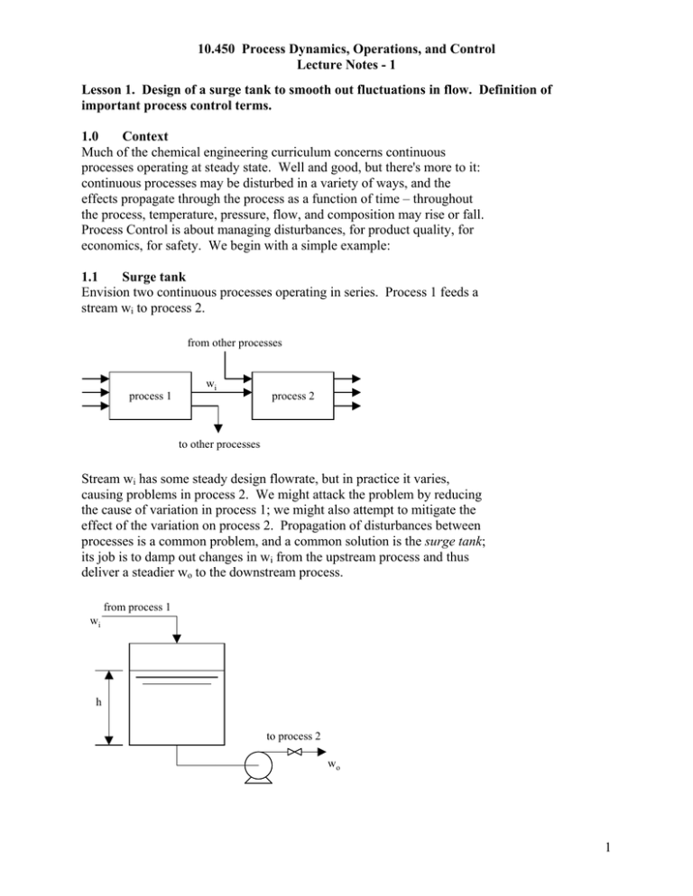
10.450 Process Dynamics, Operations, and Control Lecture Notes - 1 Lesson 1. Design of a surge tank to smooth out fluctuations in flow. Definition of important process control terms. 1.0 Context Much of the chemical engineering curriculum concerns continuous processes operating at steady state. Well and good, but there's more to it: continuous processes may be disturbed in a variety of ways, and the effects propagate through the process as a function of time – throughout the process, temperature, pressure, flow, and composition may rise or fall. Process Control is about managing disturbances, for product quality, for economics, for safety. We begin with a simple example: 1.1 Surge tank Envision two continuous processes operating in series. Process 1 feeds a stream wi to process 2. from other processes process 1 wi process 2 to other processes Stream wi has some steady design flowrate, but in practice it varies, causing problems in process 2. We might attack the problem by reducing the cause of variation in process 1; we might also attempt to mitigate the effect of the variation on process 2. Propagation of disturbances between processes is a common problem, and a common solution is the surge tank; its job is to damp out changes in wi from the upstream process and thus deliver a steadier wo to the downstream process. from process 1 wi h to process 2 wo 1 10.450 Process Dynamics, Operations, and Control Lecture Notes - 1 Notice that the inlet flow is unconstrained, and the outlet flow is pumped. Because the surge tank itself is not a steady-state process, IN does not equal OUT, and thus the liquid level will vary with time. 1.2 Designing the tank We might approach the design by (1) characterizing the inlet stream (2) specifying limits on the outlet stream (3) making a suitable process model to connect inlet with outlet Stated in this way, it's not so different from approaching a steady state process design. Inlet: suppose that the flow swings by ±40% over a 20-minute period. wi = 10,000 + 4000sin 2πt 20 (1.2.1) where flow is in kg h-1 and time in minutes. Of course, real data would be more messy, but that's just a matter of detail. One can learn a lot about the system by simplifying to the essential features. Outlet: the desired flow wo is 10,000 kg h-1. Let's be hard-nosed and insist on no variation. Process model: by instinct a chemical engineer writes a material balance. dh = wi − wo h(0) = ho dt t 1 (wi (t) − wo (t) )dt h(t) = ho + ρA ∫0 ρA (1.2.2) This is the process model; it describes how level varies with time as wi changes. Substituting (1.2.1) into (1.2.2) and integrating, we find h(t) = ho + 212 2πt 1 − cos ρA 20 (1.2.3) where height is in m, area in m2, time in minutes, and density in kg m-3. To complete the design, we must choose the tank cross-sectional area A; spending more money for a larger tank will reduce the amplitude of the level variations. 2 10.450 Process Dynamics, Operations, and Control Lecture Notes - 1 This tank has a free inlet and a pumped outlet; intuitively it seems possible that the tank may overflow or run dry. We can confirm this sobering thought by applying our tank model (1.2.2) to a persistent imbalance between wi and wo. Suppose the simple case of wi − wo = C (1.2.4) Substituting (1.2.4) into (1.2.2), we find h(t) = ho + C t ρA (1.2.5) Therefore, we should protect our tank with some automatic process control – something that will measure the level and take corrective action should the level become too high or low. 1.3 Definitions to get us started process: the equipment within some boundary, along with the streams of matter and energy that cross that boundary -- what we usually mean when we think of 'chemical process'. In this example, it's the tank, pump, piping, and fluid. disturbance: a change imposed on the process. In this example, the input stream wi varies with time. controlled variable: some feature of the process that we would like to control. It may be a stream crossing the boundary or some quantity within. We want to control it because the disturbance makes it change with time, in a way that we don't like. In this example, the controlled variable is the liquid level. set point: the desired value of the controlled variable. In this example, we have no set point, but we do want to confine the controlled variable between high and low limits. manipulated variable: some feature of the process that we adjust so that we can exert influence on the controlled variable. In most chemical processes, the manipulated variable will be the flowrate of a stream. In this example, it seems reasonable to manipulate the outlet flow. final control element: a device that adjusts the manipulated variable. If the manipulated variable is usually a stream, the final control element is usually a valve, referred to as a control valve. measured variable: most often, synonymous with the controlled variable – we measure it so that we can tell how well our control scheme is working. Of course, we may also measure the manipulated variable and other variables, as well. sensor: a measuring instrument. For chemical processes, the most common measurements are of flow (F), temperature (T), pressure 3 10.450 Process Dynamics, Operations, and Control Lecture Notes - 1 (P), level (L), and composition (A, for analyzer). The sensor will detect the value of the measured variable as a function of time. controller: the device that detects the output of the sensor, decides how seriously the controlled variable deviates from the set point, and directs the final control element in response. The controller performs calculations based on its control algorithm. transducer: this may be more than you wanted to know. The controller must be able to communicate with sensor and final element. Transducers convert and transmit signals to make this possible. There are more details, of course, but they can wait. We install a level sensor on the tank, put a control valve at the pump discharge, and connect the two with a controller. Notice the symbols: the circle containing L represents the sensor, and LC represents the controller. The control valve has a mushroom on it for reasons we'll cover later. In the schematic, the sensor communicates with the process by a solid line, and with the controller and valve by a dashed line. We call this control structure feedback control - the value of the controlled variable is fed back to a controller, which adjusts the manipulated variable in response. wi L = level sensor C = calculation or controller h L LC final control element (control valve) wo When the level sensor indicates approach to high or low limits, the controller computes a response by its algorithm and directs the control valve to open or close appropriately. The outlet flow wo may not be constant, as we wanted, but by suitable choice of tank size and control algorithm we can significantly reduce its variability, and hence the effects on downstream processes. 1.4 That’s process control? Enough for now. We've modeled a simple process, defined our terms, and sketched out a control scheme. Before we attempt to specify more about a controller, however, we must learn more about the ways in which processes might be disturbed. 4


