Magnetic Powder Cores: Design Formulas & Technical Data
MAGNETIC POWDER CORES
TECHNICAL DATA
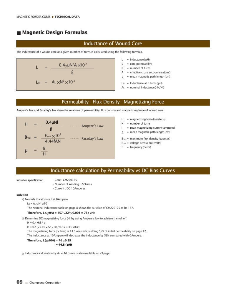
Magnetic Design Formulas
Inductance of Wound Core
The inductance of a wound core at a given number of turns is calculated using the following formula.
L =
0.4
μ N 2 A 10 -2
L
N
= A
L
N 2 10 -3
L = inductance( μ H)
μ = core permeability
N = number of turns
A = effective cross section area(cm 2 )
= mean magnetic path length(cm)
L
N
= Inductance at n turns( μ H)
A
L
= nominal Inductance(nH/N 2 )
Permeability - Flux Density - Magnetizing Force
Ampere’s law and Faraday’s law show the relations of permeability, flux density and magnetizing force of wound core.
H =
B max
=
μ =
0.4
μ Nl
B
H
E rms
10 8
4.44fAN
Ampere’s Law
Faraday’s Law
H = magnetizing force(oersteds)
N = number of turns l = peak magnetizing current(amperes)
= mean magnetic path length(cm)
B max
= maximum flux density (gausses)
E rms
= voltage across coil(volts) f = frequency (hertz)
Inductance calculation by Permeability vs DC Bias Curves
Inductor specification - Core : CM270125
- Number of Winding : 22Turns
- Current : DC 10Amperes solution a) Formula to calculate L at 0Ampere
L
N
= A
L
N 2 10 -3
The Nominal inductance table on page 8 shows the A
L value of CM270125 to be 157.
Therefore, L ( 0A) = 157 22 2 0.001 = 76 ( μH) b) Determine DC magnetizing force (H) by using Ampere’s law to achieve the roll off.
H = 0.4 Nl /
H = 0.4 3.14 22 10 / 6.35 = 43.5(Oe)
The magnetizing force(dc bias) is 43.5 oersteds, yielding 59% of initial permeability on page 12.
The inductance at 10Ampere will decrease the inductance by 59% compared with 0Ampere.
Therefore, L( 10A) = 76 0.59
Therefore, L( 10A) = 44.8 ( μH)
Inductance calculation by A
L vs Nl Curve is also available on 24page.
09 ::: Changsung Corporation
MAGNETIC POWDER CORES
TECHNICAL DATA
Mean Magnetic Path Length
For toroidal powder cores, the effective area(A) is the same as the cross sectional area. By definition and Ampere’s Law, the effective magnetic path length is the ratio of ampere-turns(NI) to the average magnetizing force. Using Ampere’s law and averaging the magnetizing force gives the formula for effective path length.
=
(OD -ID) ln
( OD
ID
)
OD = outside diameter of core (cm)
ID = inside diameter of core (cm)
A = core cross section (effective area)
= mean magnetic path length (cm)
Q Factor
The Q factor is defined as the ratio of reactance to the effective resistance for an inductor and thus indicates its quality. The Q of wound core can be calculated using the following formula, when neglecting the effects of self-resonance caused by the distributed capacitance resulting from the differential voltage between adjacent turns.
Q =
R dc
L
R ac
R d
Q = quality factor
= 2 frequency (hertz)
L = inductance (henries)
R dc
= DC winding resistance (ohms)
R ac
= resistance due to core loss (ohms)
R d
= resistance due to winding dielectric loss (ohms)
Core Loss
Powder cores have low hysteresis loss, minimizing signal distortion, and low residual loss. The total core loss at low flux densities is the sum of three frequency dependent losses of hysteresis loss, residual loss, and eddy current loss. The core loss is calculated from the following Legg’s equation.
R
μ ac
L
=
aB max f
cf ef
2
Eddy current loss
Residual loss
Hysteresis loss
Total loss factor
Where R ac a c
= core loss resistance (ohms)
= hysteresis loss coefficient
= residual loss coefficient e = eddy current loss coefficient
μ , L, B max, f = same as mentioned before
When a varying magnetic field passes through the core, eddy currents are induced in it. Joule heat loss by this currents is called eddy current loss. Hysteresis loss is due to the irreversible behavior in hysteresis curve and equal to the enclosed area of the loop.
The other core loss is called residual loss.
Magnetic Powder Cores ::: 10
