KCL). Branch circuit analysis is introduced and used to... of voltage and current in simple electrical networks. Measurements... ET304A
advertisement

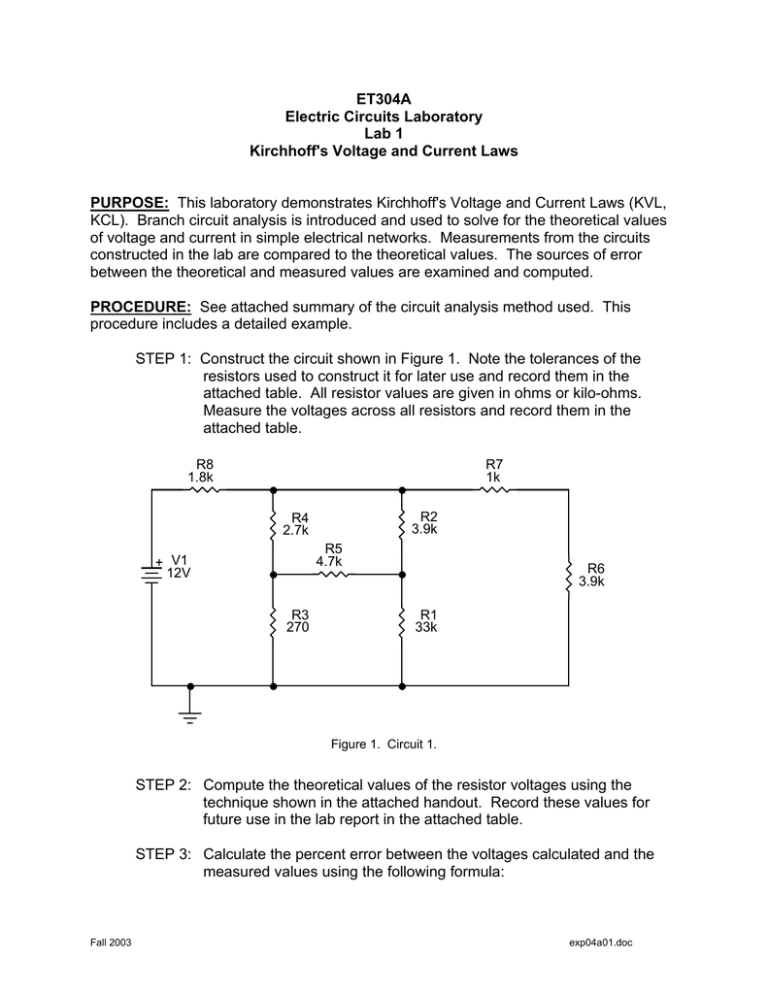
ET304A Electric Circuits Laboratory Lab 1 Kirchhoff's Voltage and Current Laws PURPOSE: This laboratory demonstrates Kirchhoff's Voltage and Current Laws (KVL, KCL). Branch circuit analysis is introduced and used to solve for the theoretical values of voltage and current in simple electrical networks. Measurements from the circuits constructed in the lab are compared to the theoretical values. The sources of error between the theoretical and measured values are examined and computed. PROCEDURE: See attached summary of the circuit analysis method used. This procedure includes a detailed example. STEP 1: Construct the circuit shown in Figure 1. Note the tolerances of the resistors used to construct it for later use and record them in the attached table. All resistor values are given in ohms or kilo-ohms. Measure the voltages across all resistors and record them in the attached table. R8 1.8k R7 1k R2 3.9k R4 2.7k R5 4.7k + V1 12V R3 270 R6 3.9k R1 33k Figure 1. Circuit 1. STEP 2: Compute the theoretical values of the resistor voltages using the technique shown in the attached handout. Record these values for future use in the lab report in the attached table. STEP 3: Calculate the percent error between the voltages calculated and the measured values using the following formula: Fall 2003 exp04a01.doc ⎡ Vmeasured − Vtheoretical ⎤ ⎢ ⎥ ⋅ 100% = error . Vtheoretical ⎣ ⎦ Where: Vmeasured = the measured value of circuit voltage, Vtheoretical = the calculated value of circuit voltage. Record these values for use in the lab report. STEP 4: Construct the circuit shown in Figure 2. Note the tolerance of the resistors used to construct the circuit and record them in the attached table. Measure all the voltages across the resistors and record them in the table provided. R1 1.8k R5 1k R9 4.7k + 10V R2 3.9k R6 4.7k R8 2.7k R3 3.9k R7 270 R4 33k Figure 2. Circuit 2. STEP 5: Use Ohm's law to calculate the current through each resistor using the measured value of resistor voltage and the measured value of resistance. Enter these currents into the data table provided. STEP 6: Calculate the percentage error for each resistor voltage and record the values in the provided table. What to Include in the Report 1.) 2.) Fall 2003 The calculations for the voltages in Circuit 1 should be included in an appendix. The calculations should be neat and orderly. These calculations should be done on Engineering paper or typing paper. The table of data for Circuit 1 should be reproduced in the report and titled. 2 exp04a01.doc 3.) The calculations for the voltages and currents in Circuit 2 should be included in an appendix. All the calculations should be neat and orderly. These calculations should be done on Engineering paper or typing paper. 4.) 5.) The data table for Circuit 2 should be reproduced in the report and titled. Analyze and comment on the percentage error between the computed and measured values for both the circuits. Consider the effects of resistor tolerance and meter accuracy in your discussion. Do all the theoretical values for voltages match the measured values within the expected error limits? If they do not, explain why. Solve for the values of Vx and Iy in Figure 3. Include the calculations in an appendix. 6.) R2 1k R1 2k Iy R3 2k + R4 5k 10V R5 1k + Vx - R6 2k R7 4k Figure 3. Circuit 3. Fall 2003 3 exp04a01.doc Lab 1 Data Tables Resistor Resistor Value (Ohms) Figure 1 Data Tolerance (%) Measured Voltage (V) Calculated Voltage (V) Error (%) R1 R2 R3 R4 R5 R6 R7 R8 Resistor Resistor Value (Ohms) Tolerance (%) Figure 2 Data Measured Calculated Voltage (V) Resistor Currents Calculated Voltage R1 R2 R3 R4 R5 R6 R7 R8 R9 Figure 2 Resistor Measurements Resistor Marked Value Measured (ohms) Value (ohms) R1 R2 R3 R4 R5 R6 R7 R8 R9 Fall 2003 4 exp04a01.doc Error (%)


