Packet Tracer Multiuser - Tutorial (Instructor Version)
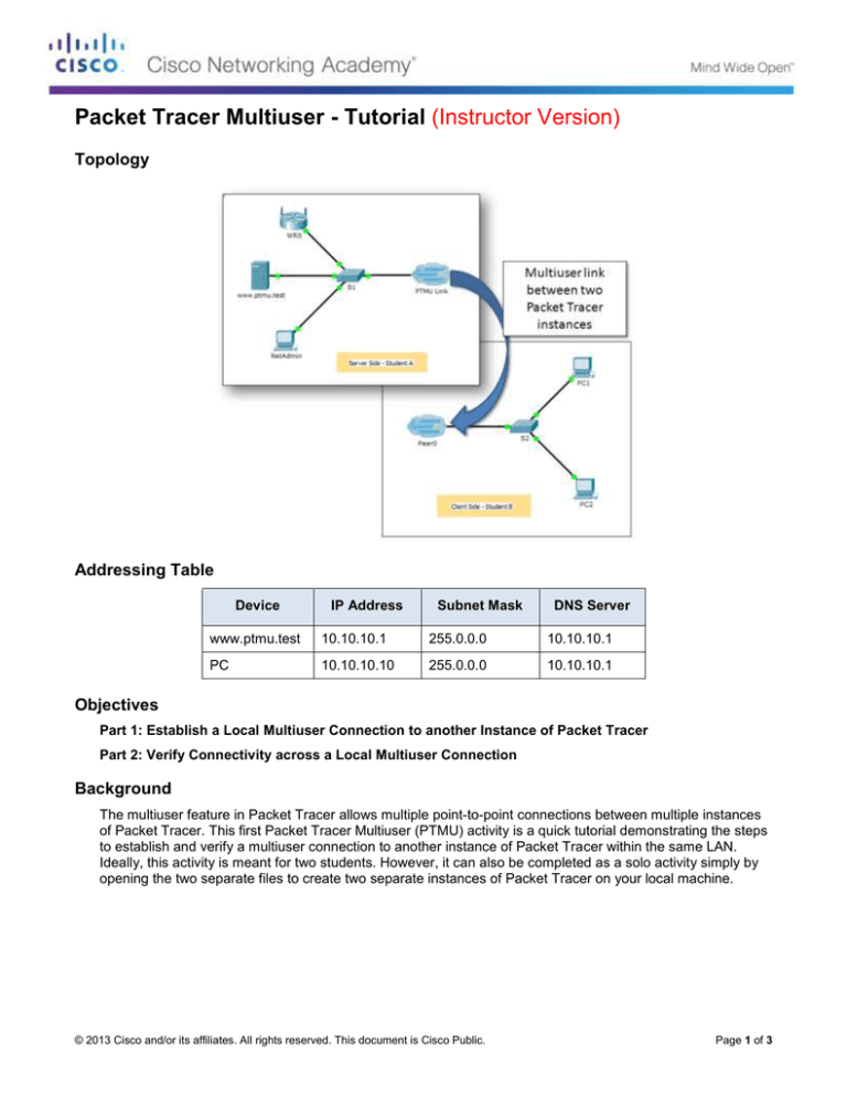
Topology
Addressing Table
Device
IP Address
Subnet Mask
DNS Server
www.ptmu.test
10.10.10.1
255.0.0.0
10.10.10.1
PC
10.10.10.10
255.0.0.0
10.10.10.1
Objectives
Part 1: Establish a Local Multiuser Connection to another Instance of Packet Tracer
Part 2: Verify Connectivity across a Local Multiuser Connection
Background
The multiuser feature in Packet Tracer allows multiple point-to-point connections between multiple instances
of Packet Tracer. This first Packet Tracer Multiuser (PTMU) activity is a quick tutorial demonstrating the steps
to establish and verify a multiuser connection to another instance of Packet Tracer within the same LAN.
Ideally, this activity is meant for two students. However, it can also be completed as a solo activity simply by
opening the two separate files to create two separate instances of Packet Tracer on your local machine.
© 2013 Cisco and/or its affiliates. All rights reserved. This document is Cisco Public.
Page 1 of 3
Packet Tracer Multiuser - Tutorial
Part 1: Establish a Local Multiuser Connection to Another Instance of
Packet Tracer
Step 1: Select a partner and determine the role for each student.
a. Find a fellow classmate with whom you will cooperate to complete this activity. Your computers must both
be connected to the same LAN.
b. Determine which of you will play the server side and which of you will play the client side in this activity.
-
The server side player opens Packet Tracer Multiuser - Tutorial - Server Side.pka.
-
The client side player opens Packet Tracer Multiuser - Tutorial - Client Side.pka.
Note: Solo players can open both files and complete the steps for both sides.
Step 2: Server Side Player - Configure the server side of the PTMU link.
The client side player must have the IP address, port number, and password used by the server side player
before the client side player can create a connection to the server side player.
a. Configure Packet Tracer to be ready for an incoming connection by completing the following steps:
1) Click the Extensions menu, then Multiuser, then Listen.
2) You have two Local Listening Addresses. If there are more than two listed, refer to the first two only.
The first one is the real IP address of the server side player’s local machine. It is the IP address your
computer uses to send and receive data. The other IP address (127.0.0.1) can only be used for
communications within your own computer’s environment.
3) The port number is listed next to your IP addresses and in the Port Number field. If this is the first
instance of Packet Tracer you opened on your computer, then the port number will be 38000.
However, if you have multiple instances open, it will increment by 1 for each instance (38001, 38002,
etc.). The port number is required by the client side player to configure the multiuser connection.
4) The password is set to cisco, by default. You can change it, but it is not necessary for this activity.
5) Tell the client side player your IP address, port number, and password. The client side player will
need these three pieces of information to connect to your Packet Tracer instance in Step 3.
6) In the Existing Remote Networks section, you must click Always Accept or Prompt radio button for
the client side player to successfully connect.
7) In the New Remote Networks section, confirm that the Always Deny radio button is enabled. This
will prevent the client side player from creating a new link that is not specified in this activity.
8) Click OK.
b. Click the Multiuser Connection icon (represented as a cloud with three lines). Then click the Remote
Network icon and add a Remote Network to the topology.
c.
Click the Peer0 name and change it to PTMU Link (it is case-sensitive).
d. Click the PTMU Link cloud and verify that the Connection Type is Incoming and that the Use Global
Multiuser Password check box is enabled.
e. Click the Connections icon and choose the solid-black Copper Straight-Through connection.
f.
Click S1 and choose the GigabitEthernet1/1 connection. Then click PTMU Link > Create New Link.
Step 3: Client Side Player - Configure the client side of the PTMU link.
a. Record the following information supplied to you by the server side player:
© 2013 Cisco and/or its affiliates. All rights reserved. This document is Cisco Public.
Page 2 of 3
Packet Tracer Multiuser - Tutorial
IP Address: _________________________________________
Port Number: ________________________________________
Password (cisco, by default) ___________________________
b. The client side player must add a Remote Network to the topology using the following directions: Click
the Multiuser Connection icon (represented as a cloud with three lines). Then click the Remote
Network icon and add a Remote Network to the topology.
c.
Click the Peer0 cloud and change the Connection Type to Outgoing.
1) In the Peer Address field, enter the server side IP address you recorded in Step 3a.
2) In the Peer Port Number field, enter the server side port number you recorded in Step 3a.
3) In the Peer Network Name field, enter PTMU Link. This is case-sensitive.
4) In the Password field, enter cisco or the password configured by the server side player.
5) Click Connect.
d. The Peer0 cloud should now be yellow, indicating that the two instances of Packet Tracer are connected.
e. Click the Connections icon and choose the solid-black Copper Straight-Through connection.
f.
Click S2 and choose the GigabitEthernet1/1 connection. Then click Peer0 > Link 0 (S1 GigabitEthernet
1/1).
The Peer0 cloud on the client side player and the PTMU Link cloud on the server side player should now
both be blue. After a short period, the link light between the switch and the cloud will transition from
amber to green.
The multiuser link is now established and ready for testing.
Part 2: Verify Connectivity Across a Local Multiuser Connection
Step 1: Configure IP addressing.
a. The server side player configures the www.ptmu.test server with the IP address 10.10.10.1, the subnet
mask 255.0.0.0, and the DNS server address 10.10.10.1.
b. The client side player configures the PC with the IP address 10.10.10.10, the subnet mask 255.0.0.0, and
the DNS server address 10.10.10.1.
Step 2: Verify connectivity and access a web page on the server side.
a. The server side player should now be able to ping the PC in the client side player instance of Packet
Tracer.
b. The client side player should now be able to ping the www.ptmu.test server.
c.
The client side player should also be able to open the web browser and access the web page at
www.ptmu.test. What is displayed on the web page? Congratulations! You successfully verified a Packet
Tracer multiuser connection.
© 2013 Cisco and/or its affiliates. All rights reserved. This document is Cisco Public.
Page 3 of 3


