Capacitors - English wiki for Mo og Øyrane
advertisement

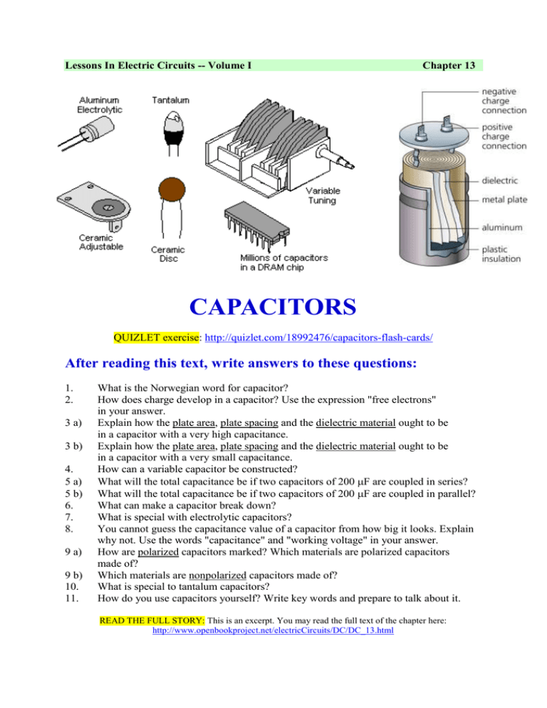
Lessons In Electric Circuits -- Volume I Chapter 13 CAPACITORS QUIZLET exercise: http://quizlet.com/18992476/capacitors-flash-cards/ After reading this text, write answers to these questions: 1. 2. 3 a) 3 b) 4. 5 a) 5 b) 6. 7. 8. 9 a) 9 b) 10. 11. What is the Norwegian word for capacitor? How does charge develop in a capacitor? Use the expression "free electrons" in your answer. Explain how the plate area, plate spacing and the dielectric material ought to be in a capacitor with a very high capacitance. Explain how the plate area, plate spacing and the dielectric material ought to be in a capacitor with a very small capacitance. How can a variable capacitor be constructed? What will the total capacitance be if two capacitors of 200 F are coupled in series? What will the total capacitance be if two capacitors of 200 F are coupled in parallel? What can make a capacitor break down? What is special with electrolytic capacitors? You cannot guess the capacitance value of a capacitor from how big it looks. Explain why not. Use the words "capacitance" and "working voltage" in your answer. How are polarized capacitors marked? Which materials are polarized capacitors made of? Which materials are nonpolarized capacitors made of? What is special to tantalum capacitors? How do you use capacitors yourself? Write key words and prepare to talk about it. READ THE FULL STORY: This is an excerpt. You may read the full text of the chapter here: http://www.openbookproject.net/electricCircuits/DC/DC_13.html 2 Electric fields and capacitance Whenever an electric voltage exists between two separated conductors, an electric field is present within the space between those conductors. Fields have two measures: a field force and a field flux. The field force is the amount of "push" that a field exerts over a certain distance. The field flux is the total quantity, or effect, of the field through space. Capacitors have two conductive plates (usually metal) close to each other. When a voltage is applied across the two plates of a capacitor, a concentrated field flux is created between them, allowing a significant difference of free electrons (a charge) to develop between the two plates: As the electric field is established by the applied voltage, extra free electrons are forced to collect on the negative conductor, while free electrons are "robbed" from the positive conductor. The greater the difference of electrons on opposing plates of a capacitor, the greater the field flux, and the greater "charge" of energy the capacitor will store. Dielectric, permittivity and capacitance The insulating material between the plates has a special name: dielectric. Not all dielectric materials are equal: the extent to which materials inhibit or encourage the formation of electric field flux is called the permittivity of the dielectric. 3 The measure of a capacitor's ability to store energy for a given amount of voltage drop is called capacitance. Capacitance is symbolically denoted with a capital "C," and is measured in the unit of the Farad, abbreviated as "F." The three factors affecting capacitance PLATE AREA: Greater plate area gives greater capacitance; less plate area gives less capacitance. PLATE SPACING: Further plate spacing gives less capacitance; closer plate spacing gives greater capacitance. DIELECTRIC MATERIAL: Greater permittivity of the dielectric gives greater capacitance; less permittivity of the dielectric gives less capacitance. "Relative" permittivity means the permittivity of a material, relative to that of a pure vacuum. Glass, for instance, with a relative permittivity of 7, has seven times the permittivity of a pure vacuum. 4 The following photograph shows an example of a variable capacitor using a set of interleaved metal plates and an air gap as the dielectric material: As the shaft is rotated, the degree to which the sets of plates overlap each other will vary, changing the effective area of the plates between which a concentrated electric field can be established. This particular capacitor has a capacitance in the picofarad range, and finds use in radio circuitry. Series and parallel capacitors When capacitors are connected in series, the total capacitance is less than any one of the series capacitors' individual capacitances. If two or more capacitors are connected in series, the overall effect is that of a single (equivalent) capacitor having the sum total of the plate spacings of the individual capacitors. As we've just seen, an increase in plate spacing, with all other factors unchanged, results in decreased capacitance. Formula: 5 When capacitors are connected in parallel, the total capacitance is the sum of the individual capacitors' capacitances. If two or more capacitors are connected in parallel, the overall effect is that of a single equivalent capacitor having the sum total of the plate areas of the individual capacitors. As we've just seen, an increase in plate area, with all other factors unchanged, results in increased capacitance. Formula: REVIEW: Capacitances diminish in series. Capacitances add in parallel. Practical considerations Working voltage: If too much voltage is applied, the "breakdown" rating of the dielectric material may be exceeded, resulting in the capacitor internally short-circuiting. Polarity: Some capacitors are manufactured so they can only tolerate applied voltage in one polarity but not the other. These are called electrolytic capacitors, and their polarity is clearly marked. 6 Physical Size: For most applications in electronics, minimum size is the goal. With capacitors, there are two major limiting factors to the minimum size of a unit: working voltage and capacitance. And these two factors tend to be in opposition to each other. For any given choice in dielectric materials, the only way to increase the voltage rating of a capacitor is to increase the thickness of the dielectric. However, as we have seen, this will decrease capacitance. Take the following two photographs for example: This is a fairly large capacitor in physical size, but it has quite a low capacitance value: only 2 µF. However, its working voltage is quite high: 2000 volts! 7 The thinner dielectric layer gives it a much greater capacitance (20,000 µF) and a drastically reduced working voltage (35 volts continuous, 45 volts intermittent). Here are some samples of different capacitor types, all smaller than the units shown previously: 8 9 The electrolytic and tantalum capacitors are polarized (polarity sensitive), and are always labeled as such. The electrolytic units have their negative (-) leads distinguished by arrow symbols on their cases. Some polarized capacitors have their polarity designated by marking the positive terminal. The large, 20,000 µF electrolytic unit shown in the upright position has its positive (+) terminal labeled with a "plus" mark. Ceramic, mylar, plastic film, and air capacitors do not have polarity markings, because those types are nonpolarized (they are not polarity sensitive). Capacitors are very common components in electronic circuits. Take a close look at the following photograph -- every component marked with a "C" designation on the printed circuit board is a capacitor: 10 Some of the capacitors shown on this circuit board are standard electrolytic: C30 (top of board, center) and C36 (left side, 1/3 from the top). Some others are a special kind of electrolytic capacitor called tantalum, because this is the type of metal used to make the plates. Tantalum capacitors have relatively high capacitance for their physical size. The following capacitors on the circuit board shown above are tantalum: C14 (just to the lower-left of C30), C19 (directly below R10, which is below C30), C24 (lower-left corner of board), and C22 (lower-right). Examples of even smaller capacitors can be seen in this photograph: 11 The capacitors on this circuit board are "surface mount devices" as are all the resistors, for reasons of saving space. Following component labeling convention, the capacitors can be identified by labels beginning with the letter "C".


