International Journal of Science, Engineering and Technology Research (IJSETR)
Volume 1, Issue 1, July 2012
Universal Timer using Microcontroller for Home
Appliances ; Software Implementation
Su Mon Htet1, Zaw Myo Tun2
Abstract— This paper deals with the design, development
and implementation of microcontroller based universal On-Off
timer for home appliances. This system is developed for the
users to control the operation of any home appliances. The
system is divided into two parts; software implementation and
hardware implementation. This paper mainly concerns with
software implementation of the system. Man has no time to wait
for a particular appliance to on for a particular period in
modern world. Under this control, the appliance can be on and
off. It mainly consists of a keypad, microcontroller unit, relay
driver circuits and LCD display. The user can set any of the
time given in the timer switch using keypad. The settings are
stored in the microcontroller and the details are displayed in the
LCD display. The appliance is controlled to run for the
particular period by the timer switch. The timer switch
automatically makes the appliance off if the particular period is
over. This system is efficient, reliable and user friendly.
Index Terms— Timer, Microcontroller, Keypad, LCD,
Relay driver
program is written in PIC Basic Pro language and run in PIC
microcontroller. The universal timer based on
microcontroller will help to control home appliance
comfortably and time efficiently. This paper continues in the
following pattern: part 2 presents the hardware
implementation for the system, part 3 describes the software
implementation of the system, part 4 deals with discussion of
result and the conclusion is presented in part 5. The overall
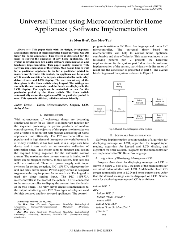
block diagram of the system is shown in Figure 1.
LCD
Display
Timer
Setting Input
Manuscript received Oct 15, 2011.
Su Mon Htet, Electronic Department, Mandalay Technological
University.,
(sansan7487@gamil.com).
Mandalay,
Myanmar,
09-428154620
Zaw Myo Tun, Electronic Department, Mandalay Technological
University.,, Mandalay, Myanmar, 09-444045182., (zawmyotun.mtu@
gmail.com).
Relay 1
(motor, air
conditioner)
Driver
Circuit 2
Relay 2
(Ricecooker,fan)
PIC
Microcontroller
I. INTRODUCTION
With advancement of technology things are becoming
simpler and easier for us. Timer is an important function for
the sequence processing or precise producer of modern
control systems. The objective of this paper is to investigate a
cost effective solution that will provide controlling of home
appliances time efficiently. The PIC microcontrollers are
popular and in high demand throughout the world because it
is widely available, it has low cost, it is a large user base
device and it can work as an extensive collection of
application notes. This system aims to program and design
the required timing sequence for the automatic control
system. The maximum time the user can set is limited to 18
hours due to program memory. In this system, four sections
will be considered. These are power supply unit, input
switches for setting selection, PIC 16F877A microcontroller
unit and relay driver circuit. Power supply circuit is designed
to generate the require power for entire circuit. The keypad is
used for timer setting input. The PIC 16F877A
microcontroller is the heart of the system. LCD is connected
to the microcontroller to display the current time the details
of the two timers. The relay driver circuit is implemented to
the output interfacing with PIC. Two types of relay are used
for high powered and low powered appliances. The control
Driver
Circuit 1
Fig. 1.Overall Block Diagram of the System
II. SOFTWARE IMPLEMENTATION
Software implementation section consists of algorithm for
displaying message on LCD, algorithm for keypad input
reading, algorithm for keypad and LCD display, and
algorithm for timer counter. Programs for the microcontroller
are implemented in PIC Basic Pro language.
A. Algorithm of Displaying Message on LCD
Program flow chart for displaying message on LCD is
shown in figure 2. First of all, the ports of the microcontroller
are initialized to interface with LCD. And then the clear LCD
screen command is sent to LCD and home cursor is set. After
that, the desired message can be displayed on LCD. Source
code for displaying message on LCD is as follows;
lcdout $FE, 1
RPT:
lcdout $FE, 2
lcdout "Hello World! "
pause 1000
lcdout $FE, $C0
lcdout "I am Su Mon Htet."
goto RPT
end
1
All Rights Reserved © 2012 IJSETR
International Journal of Science, Engineering and Technology Research (IJSETR)
Volume 1, Issue 1, July 2012
Endif
If (row4 == 0) Then
' key # is down
Endif
goto loop
start
Initialize Inputs,
Output Ports
Clear LCD screen
start
Set home cursor
Initialize Inputs,
Output Ports
Clear LCD screen
Display Message
Display Message
“Press Any Key
End
Fig .2. Displaying Message on LCD
B. Algorithm for Keypad Input Reading
Program flow chart for keypad input reading is shown in
figure 3. First of all, the inputs and outputs ports are
initialized. And then LCD screen is cleared and display
message to press the key. The input pins of the
microcontroller are checked until the key is pressed. When
any key is pressed, microcontroller checks which key is
pressed and displays the pressed key on LCD. The following
shows the keypad polling loop in basic pro language.
loop:
' Check column 1
Low col1 : High col2 : High col3
If (row1 == 0) Then
high PORTD.0 ' key 1 is down
Endif
If (row2 == 0) Then
HIGH PORTD.1' key 4 is down
Endif
If (row3 == 0) Then
' key 7 is down
Endif
If (row4 == 0) Then
' key . is down
Endif
' Check column 2
High col1 : Low col2 : High col3
If (row1 == 0) Then
' key 2 is down
Endif
If (row2 == 0) Then
' key 5 is down
Endif
If (row3 == 0) Then
' key 8 is down
Endif
If (row4 == 0) Then
' key 0 is down
Endif
' Check column 3
High col1 : High col2 : Low col3
If (row1 == 0) Then
' key 3 is down
Endif
If (row2 == 0) Then
' key 6 is down
Endif
If (row3 == 0) Then
' key 9 is down
No
Key Press?
Yes
Check which
key is pressed
Display pressed
key on LCD
End
Fig. 3. Flowchart for Keypad Input Reading
C. Algorithm for Timer Counter Display
Timer counting is the essential part of the microcontroller
based home appliance system since the user can set the on/off
timing for home appliances in smart home system. The user
needs to set the timing using keypad. The microcontroller
stores the key pressed numbers and calculates the count for
timer. After that, the timer is counted down and when the
setting time is reached, the PIC sends the command to the
output pin to show the setting time is completed. In this
research, LED is connected to the output pin to describe the
result. The program is implemented to turn on and off the
LED three times when the setting time is completed to see the
result quite clear.
start
Check which
key is pressed
Initialize Inputs,
Output Ports
Clear LCD screen
Display Message
“Press Any Key
Calculate count
for timer
Decrease count
Display on LCD
No
Key Press?
Yes
Turn on/off
LED 3 times
End
No
No
Count = 0 ?
Yes
Fig. 4. Flowchart for Timer Counter Display
D. Overall System Flow and Algorithm for Timer Setting
There are six subroutines included in the program. They
are subroutines for key test from keypad, for second count,
for key number calculation, for time calculation, for asking
2
All Rights Reserved © 2012 IJSETR
International Journal of Science, Engineering and Technology Research (IJSETR)
Volume 1, Issue 1, July 2012
the timer setting, and for calculating the interval of timer on
conditions.
First of all,. “ON” time or “OFF” time of timer 1 and timer
2 will be asked. Then the microcontroller will calculate the
duration time for timer 1 and timer 2 and then the output
signal will be set when the setting time is completed. The
system flow procedure is shown in figure 5.
.
IV. DEVELOPING HEX CODE AND DOWNLOADING HEX CODE
INTO MICROCONTROLLER
Developing Hex Code and Downloading hex code into
microcontroller.
To develop the PIC and LCD interfacing circuit, the
program is written in Microcode Studio Plus window and
compiled. If compiling process succeeds, the Microcode
Studio creates hex code for microcontroller. Figure 5.2 shows
software development window with Microcode Studio and
hex code created for microcontroller.
Fig. 8. Software Development Window with Microcode Studio and Hex
Code Created for Microcontroller
Fig. 5. Overall System Flow for the Home Automation System
III. RESULTS
In this system, the user has firstly set the desired hours,
minutes and seconds for two timers. After that, the
microcontroller start comparing and counting the times.
Figure 6 shows the condition when timer 1 ON time is
reached. The output signal is described with a LAMP. Figure
6 shows the condition when timer 2 ON time is reached. The
output signal is described with a LAMP.
The hex code is created by compiling the program in
Microcode studio Plus software. This code is burnt in
microcontroller using PIC kit 2 programmer and interfacing
software. Figures 2 and 3 shows the blank check of the
microcontroller, the importing hex file into microcontroller
and burning the hex file to the microcontroller using PIC kit 2
programmer and interfacing software.
Fig. 9. PIC kit2 Programmer checking whether the device is blank or not
Fig. 6. Simulation Result for timer 2 is ON
.
Fig. 7.Simulation Result for timer 1 is ON
Fig. 10. Importing Hex file to the Microcontroller
3
All Rights Reserved © 2012 IJSETR
International Journal of Science, Engineering and Technology Research (IJSETR)
Volume 1, Issue 1, July 2012
V. SUMMARY
The hardware design and software implementation of the
timer system is described. The desired programming
software is used in PIC Basic Pro. The system can count the
two timers at the same time and switch on and off for the
particular period. The PIC 16F877A microcontroller is the
heart of the system. The twelve-key matrix keypad , 4×20
LCD and two types of relay driver are used. The user can use
this system time efficiently and comfortably.
VI. CONCLUSION
The main motivation of this system is to develop and
implement a simple and inexpensive universal timer for
home appliances.The maximum time is limited to 18
hours.The Proteus simulation software and PIC Basic Pro
programming language are used. How to implement the PIC
program is described with flowchart. Proteus test for the
system is described. A flexible and easy way for controlling
home appliance is created.
REFERENCES
[1]
Microchip, PICMicro Mid-Range MCU Family Reference Manual,
DS33023A, Microchip Technology Inc, 1997.
[2] Design and Development of Activation and Controlling of Home
Automation System VIA SMS through Microcontroller, Ch. Naga Koti
Kumar*, Y.V. Raghu Babu**,A. Gamya***, P.Jainath****, M.
Vijay*****(Mar-Apr 2012,pp.1349-1352)
[3] Microcontroller based IR Remote Control Signal Decoder for Home
Application, Nhivekar G.S and Mudholker R.R,2011
[4] Microcontroller Based Home Automation System With Security,
Inderpreet Kaur (Asstt. Prof.), IJACSA,Vol. 1,No.6,December 2010.
[5] Home appliances Controlling Using Windows Phone 7, Chesti Altaff
Hussain, K. Vijaya Lakshmi, International Journal of Advanced
Research in Electrical, Electronics and Instrumentation
Engineering,Vol 2,Issue 2, February 2013
[6] “DC Motorised Treadmill For Home” http://treadmill.jkexer.com/en/2
1789 60763/product/Motorized Treadmills id342279.html
[7] Herman, Stephen L. Electric Motor Control. (http://books.google.
com/books?id=Yxy8WRWfIy0C&pg=PA12&dq=dc+electric+motor
+protection&hl=en&ei=xwC8TrefFOHq0gHW4czfCQ&sa=X&oi=bo
ok_result&ct=result&resnum=9&ved=0CHAQ6AEwCA#v=onepage
&q=dc%20electric%20motor%20protection&f=false) 9th ed. Delmar,
Cengage Learning, 2009. Page 12
[8] Malcolm Barnes. Practical variable speed drives and power electronics.
(http://books.google.com/books?id=LxW9F9WCixcC&pg=PA151&d
q=dc+motor+insulation+failures&hl=en&ei=UCrATsnlK-j30gG_s7i3
BA&sa=X&oi=book_result&ct=result&resnum=3&ved=0CD4Q6AE
wAjgK#v=onepage&q&f=false) Elsevier, Newnes, 2003. Page 151
4
All Rights Reserved © 2012 IJSETR

