Curent balance / Force acting on a currentcarrying conductor with Cobra4
TEP
Related topics
Uniform magnetic fields, magnetic induction (or magnetic flux densitiy), Lorentz force, moving charges,
current.
Principle
The force acting on a current carrying conductor loop in a uniform magnetic field (Lorentz force) is
measured with a force sensor. The uniform magnetic field is generated by an electromagnet. Conductor
loops of various sizes are suspended between the pole pieces of the electromagnet and the Lorentz
force is determined as a function of the current and magnetic induction. The magnetic induction can be
varied with the coil current.
Equipment
1
3
1
2
1
1
1
1
2
2
1
1
1
1
1
1
1
3
Cobra4 Wireless Manager
Cobra4 Wireless-Link
Cobra4 Sensor-Unit Force ± 4 N
Cobra4 Sensor-Unit Electricity
Power supply, universal
Bridge receiver 250 VAC/5 A
On/Off switch
Pole pieces, rectangular, 1 pair
Coil, 300 turns
Base for iron cores
Iron core, U-shaped, laminated
Wire loop, 𝑙 = 12.5 mm, 𝑛 = 1
Wire loop, 𝑙 = 25 mm, 𝑛 = 1
Wire loop, 𝑙 = 50 mm, 𝑛 = 1
Wire loop, 𝑙 = 50 mm, 𝑛 = 2
Tripod base PHYWE
Support rod, square, 𝑙 = 400 mm
Right angle clamp
12600-00
12601-00
12642-00
12644-00
13500-93
06031-11
06034-01
11081-02
06513-01
06508-00
06501-00
11081-05
11081-06
11081-08
11081-07
02002-55
02026-55
02040-55
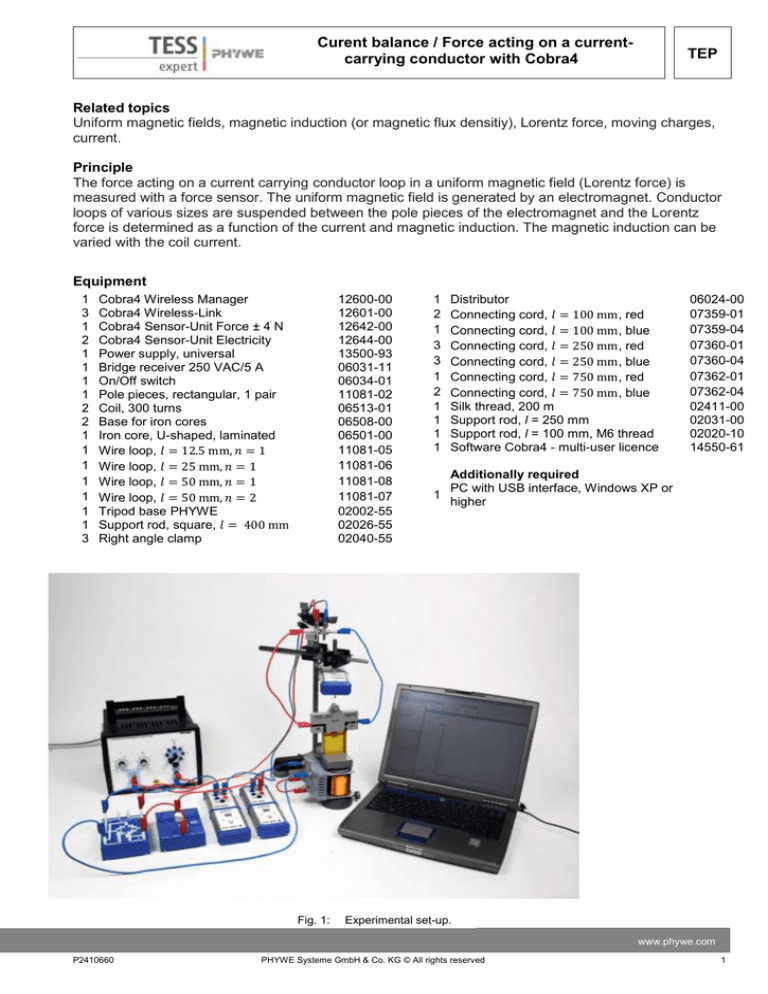
Fig. 1:
1
2
1
3
3
1
2
1
1
1
1
Distributor
Connecting cord, 𝑙 = 100 mm, red
Connecting cord, 𝑙 = 100 mm, blue
Connecting cord, 𝑙 = 250 mm, red
Connecting cord, 𝑙 = 250 mm, blue
Connecting cord, 𝑙 = 750 mm, red
Connecting cord, 𝑙 = 750 mm, blue
Silk thread, 200 m
Support rod, l = 250 mm
Support rod, l = 100 mm, M6 thread
Software Cobra4 - multi-user licence
06024-00
07359-01
07359-04
07360-01
07360-04
07362-01
07362-04
02411-00
02031-00
02020-10
14550-61
Additionally required
PC with USB interface, Windows XP or
1
higher
Experimental set-up.
www.phywe.com
P2410660
PHYWE Systeme GmbH & Co. KG © All rights reserved
1
TEP
Curent balance / Force acting on a current-carrying
conductor with Cobra4
Tasks
1. The force 𝐹 is to be measured as a function of the current 𝐼𝐿 in the conductor loop with a constant
magnetic induction 𝐵 and for conductor loops of various sizes. The magnetic induction 𝐵 is to be
calculated.
2. The force 𝐹 is to be measured as a function of the coil current 𝐼𝑀 for a conductor loop. In the range
under consideration the magnetic induction 𝐵 is proportional to the coil current 𝐼𝑀 with sufficient accuracy.
Set-up and procedure
Set up the equipment as seen in Fig. 1. The coils of the electromagnet are connected in series and are
connected to the bridge rectifier which is on the other side connected to the AC output of the power supply. In the circuit on the coil's side of the rectifier a switch and the Cobra4 Sensor-Unit Electricity are inserted, the Sensor-Unit Electricity is connected to the Wireless Link. For the first part of the experiment,
a fixed voltage of 12 𝑉 AC is selected and the corresponding current 𝐼𝑀 in the coils is measured. The
conductor loops are suspended on the Cobra4 Sensor-Unit Force 4 N force sensor and are connected
with two connecting cords to the distributor and over the other Cobra4 Sensor-Unit Electricity and over
another Wireless Link to the direct voltage output of the power supply unit. It is important to look for the
orientation of the conductor loop between the pole pieces. It has to be aligned parallel to the pole pieces
and is not hanging crooked. Now in your experimental setup should be three Wireless Links present,
which are connected by a Wireless Manager with the computer. Now press the Start-Button on the Wireless Links and start the "measure" program. Now you need to download the file for this experiment. Before recording a measurement, click the "Tara" button in each measurement menus. Start and stop the
measurement with the start- and stop-button.
1. Place the pole pieces on the electromagnet with their edges parallel and with an air gap of 1 𝑐𝑚 and
hang the conductor loop with 𝑙 = 12.5 𝑚𝑚 on the force sensor. Click the "Tara" button (after clicking
the Newton module symbol). The horizontal section of the conductor is to run perpendicular to the
field lines and is to be in the middle of the uniform field. Now start data recording with the "Start
measurement" button and increase the current in the conductor loop 𝐼𝐿 in steps of 1 𝐴 with the control on the power unit up to 5 𝐴 . For every step of 𝐼𝐿 switch the current 𝐼𝑀 of the two coils on and off
with the switch (maybe several times) so you can evaluate the change of the force easily seeing only the effect of the magnetic field without needing to pay attention to an offset because of sensor drift
or a bad tare because of forces on the conductor strips. Stop data recording. Repeat the procedure
with the other conductor loops. The obtained curves may look like Fig.2, here with the current decreased in steps of 1 𝐴.
2
PHYWE Systeme GmbH & Co. KG © All rights reserved
P2410660
Curent balance / Force acting on a currentcarrying conductor with Cobra4
TEP
2. With the conductor loop 𝑙 = 50 𝑚𝑚, 𝑛 = 2 record a measurement keeping the current 𝐼𝐿 of the loop
constant at 5 𝐴 but varying the current through the magnet coils IM by setting different voltages on
the power supply. Record the data in the same way as above. The obtained curves may look like
Fig. 3.
Fig. 2:
Typical data for task 1.
Theory and evaluation
Fig. 3:
Typical data for task 3.
⃗ , a force 𝐹 (Lorentz force) acts on a charge 𝑞 moving with
In a magnetic field with a magnetic induction 𝐵
velocity 𝑣 :
www.phywe.com
P2410660
PHYWE Systeme GmbH & Co. KG © All rights reserved
3
TEP
Curent balance / Force acting on a current-carrying
conductor with Cobra4
⃗)
𝐹 = 𝑞 ∙ (𝑣 × 𝐵
(1)
⃗ . In this experiment 𝑣 and 𝐵
⃗ are at right
The force vector 𝐹 is perpendicular to the plane through 𝑣 and 𝐵
angles. So that for the amounts of the vectors is
𝐹 =𝑞 ∙𝑣 ∙𝐵
(2)
The velocity of the charge carriers (electrons) is measured by the electric current 𝐼𝐿 in the conductor. In
the part of the conductor with length 𝑙 is
𝑞 ∙ 𝑣 = 𝐼𝐿 ∙ 𝑙
(3)
𝐹 = 𝐵 ∙ 𝐼𝐿 ∙ 𝑙
(4)
So that for the amount of 𝐹
Use the "Survey" function of the "measure" program to evaluate the obtained curves. Read out the force
differences and the current values 𝐼𝐿 ("I1"). Plot the force vs. current 𝐼𝐿 for all four conductor loops using
"Measurement" > "Enter data manually…". Several curves may be brought into one diagram with "Measurement" > "Assume channel…". Use the "Scale curves" feature "set to values" for scaling the curves in
one diagram. Fig.3 shows an example of obtained results.
Fig. 4:
4
Force on the loop vs. current through the loop with constant magnetic field.
PHYWE Systeme GmbH & Co. KG © All rights reserved
P2410660
Curent balance / Force acting on a currentcarrying conductor with Cobra4
TEP
Use the "Regression" function to evaluate the slopes of the curves. Fig.5 shows a plot slope vs. conductor length 𝑙. The resulting magnetic induction is again the slope of the curve and reads in this example
88 𝑚𝑇 = 88 (𝑚𝑁)/(𝐴𝑚). The current 𝐼𝑀 was 830 𝑚𝐴. The field is strongly dependent on the gap width of
the pole pieces – you may measure other values.
Fig. 5:
Slope of the force vs. conductor length in field.
Plot also the force vs. the current through the field generating coils 𝐼𝑀 . You should get a fairly linear relation.
www.phywe.com
P2410660
PHYWE Systeme GmbH & Co. KG © All rights reserved
5
TEP
Curent balance / Force acting on a current-carrying
conductor with Cobra4
Place for notes:
6
PHYWE Systeme GmbH & Co. KG © All rights reserved
P2410660


