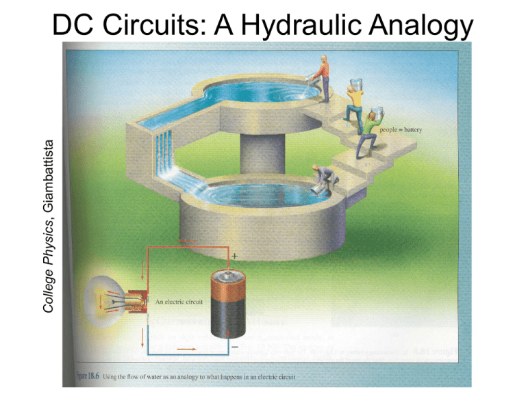
College Physics, Giambattista
DC Circuits: A Hydraulic Analogy
Resistors in Series
• When 2 or more resistors are connected end-to-end,
they are said to be in series
– Current is the same in each resistor (conservation of charge)
– Sum of potential differences across the resistors = total
potential difference across the series combination
(conservation of energy)
– Equivalent resistance of a series combination of n resistors
(from Ohm’s Law): R R R R R
eq
1
2
3
n
Resistors in Parallel
• If all of the “left” sides of a set of resistors are
connected, along with all of the “right” sides, the
resistors are in parallel
– Potential differences across the resistors are the same
– I I1 I 2 from conservation of charge (see figure below)
– Equivalent resistance of n resistors connected in parallel
(from Ohm’s Law and conservation of charge):
1
1 1
1
1
Req R1 R2 R3
Rn
Household Circuits
CQ 1: The circuit shown below has three resistors
connected in parallel to a battery. When an additional
resistor, R4, is added to the circuit:
A)
B)
C)
D)
The voltage produced by the battery will increase.
The voltage produced by the battery will decrease.
The current produced by the battery will decrease.
The power produced by the battery will increase.
Example Problem #18.5
(a) Find the equivalent
resistance between points
a and b in the circuit
diagram. (b) Calculate the
current in each resistor if a
potential difference of
34.0 V is applied between
points a and b.
Solution (details given in class):
(a) 17.1 W
(b) I4 = I9 = 1.99 A, I7 = 1.17 A, I10 = 0.818 A
CQ 2: Interactive Example Problem:
Fun with Light Bulbs
What would happen if one of the light bulbs
were removed from the parallel circuit of light
bulbs as shown in class?
A) All of the remaining bulbs go out.
B) The remaining bulbs remain illuminated, but
with larger brightness.
C) The remaining bulbs remain illuminated with
the same brightness.
D) The remaining bulbs remain illuminated, but
with smaller brightness.
Kirchhoff’s Rules and Complex DC Circuits
• In more complex DC circuits, resistor combinations
cannot be reduced to a single equivalent resistor
• These complex circuits can be analyzed using rules
known as Kirchhoff’s rules:
– The current that flows into a junction (any (I1 = I2 + I3)
electrical connection) must equal the current
that flows out of the same junction (“junction
rule”)
• Follows from conservation of charge
– The sum of the potential differences across all of the circuit
elements around any closed loop must be zero (“loop rule”)
• Follows from conservation of energy
• Think of taking a hike in the mountains, starting and returning at the
same spot (sum of all elevation changes must equal zero no matter
what path you take)
Kirchhoff’s Rules: Problem-Solving Strategy
• Assign symbols and directions to the currents in all
branches of the circuit
• When applying the loop rule, choose a direction for
traversing the loop and stay consistent in going
either clockwise or counterclockwise
• Summary of rules used to record voltage drops and
rises while applying loop rule:
Direction of loop travel
(loop traversal is assumed to be from
point a toward point b)
CQ 3: If all the resistors in the circuit pictured below
have equal resistances, and the current through
resistor A is 4 A, what is the current through resistor F?
A)
B)
C)
D)
2A
1A
8A
16 A
Example Problem #18.17
The ammeter shown in
the figure reads 2.00 A.
Find I1, I2, and e.
#1
I3
#2
Solution (details given in class):
I1 = 0.714 A
I2 = 1.29 A
e = 12.6 V
Example Problem #18.26
I1
I2
I3
#1
I2
#2
A dead battery is charged by connecting it to the live battery of another car with
jumper cables (see figure). Determine the current in the starter and in the dead
battery.
Solution (details given in class):
I(starter) = 1.7 102 A
I(dead battery) = 0.28 A
Example Problem #18.56
I1
I
I – I1
#1
#2
The resistor R in the figure dissipates 20 W of
power. Determine the value of R.
Solution (details given in class):
20 W or 98 W
RC Circuits
• Consider a circuit with a resistor and a capacitor in
series with a battery:
– Capacitor initially uncharged
with switch open
– When switch is closed, battery
begins to charge capacitor
plates and current passes through resistor
– Charge on capacitor varies with time:
q Q 1 e t / RC
•
•
•
•
•
Charging a capacitor
e = 2.718 … = Euler’s constant (base of natural logarithms)
Q = maximum charge = Ce (only reached at t = )
q = 0 at t = 0
t / RC
D
V
e
1
e
At any moment, DV (capacitor) = q / C
RC = constant = t = time constant of the circuit (units of seconds)
RC Circuits
• Now consider a circuit with a charged capacitor, a
resistor, and a switch:
Discharging a capacitor
– Before switch is closed, Q = Ce
– After switch is closed, capacitor discharges exponentially
with time:
q Qe t / RC
– Voltage across capacitor also decreases exponentially with
time:
DV e e t / RC
RC Circuits in Neurons
• A simplified model of axon segments incorporates
RC circuits
(College Physics, Giambattista et al.)
– Current flows through conducting axoplasm fluid (modeled
as resistor R)
– Capacitor consists of interstitial and axoplasm conducting
fluids as the plates, with the membrane and myelin sheath
acting as an insulator
– Speed of electrical impulses depend on time constant of
“RC circuit”
• Typical time constant t for humans is about 20 ms
• Speed of electrical impulse = length of axon section/t ≈ 50 m/s
Example Problem #18.34
A series combination of a 12-kW resistor and
an unknown capacitor is connected to a 12-V
battery. One second after the circuit is
completed, the voltage across the capacitor is
10 V. Determine the capacitance of the
capacitor.
Solution (details given in class):
47 mF
CQ 4: Interactive Example Problem:
RC Circuit Analysis
When the battery voltage is doubled in the
simulation, how much time does it take for the
capacitor to subsequently discharge?
A)
B)
C)
D)
0 ms
2 ms
4 ms
8 ms
(PHYSLET Physics Exploration 30.6, copyright Pearson Prentice Hall, 2004)
CQ 5: What is the net force on the dipole inside the
capacitor if the plates are separated by 1 cm?
A)
B)
C)
D)
0N
4N
8N
16 N
Electrical Safety
• Electric currents passing through the body interfere
with the operation of muscles and nervous system
• Large currents also cause burns due to energy
dissipated in tissues
• Current levels and their effects:
–
–
–
–
1 mA: usually nothing more than unpleasant sensation
> 5 mA: Harmful effects start to occur
10 – 20 mA: muscle contractions or paralysis
100 – 300 mA: ventricular fibrillation if near heart
• Most of the electrical resistance of the body is due to
the skin
– Internal fluids are good conductors due to ions
– Total resistance across dry body ~ 10 – 1000 kW
– Total resistance across wet body ~ 1 kW or less
Electrical Safety
• A short circuit (low-resistance path) may occur
between circuitry inside an appliance and the metal
on the outside of appliance
– Person touching appliance would then have at least one
hand at 120 V with respect to ground
– If feet are in a wet tub (which makes good electrical
contact with grounded water pipes), resistance may be as
low as 500 W
– Electrical resistance from one damp hand
to another is about 1600 W (still bad)
– Three-pronged plugs connect appliance
casing to ground
– GFI outlets interrupt circuit if current
5 mA is detected “leaking” to ground


