Final Poster
advertisement

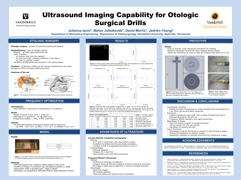
Ultrasound Imaging Capability for Otologic Surgical Drills Julianna 1Department 1 Ianni , Meher 1 Juttukonda , 1 Morris , David Jadrien 2 Young of Biomedical Engineering, 2Department of Otolaryngology (Vanderbilt University, Nashville, Tennessee) OTOLOGIC SURGERY RESULTS PROTOTYPE 8.89 MHz Simulation 40 150 •Otologic surgery: purpose of restoring hearing and balance •Design • Uses an annular (ring) ultrasound transducer for imaging • Positions transducer to allow for quick imaging during surgery • Allows the transducer to move to clear the surgical area when not in use 30 20 50 Echo Amplitude Amplitude 100 Amplitude •Mastoidectomy: type of otologic surgery •Mastoid – air-filled space behind the ear •Uses of surgery •to remove cells from the mastoid •to treat anti-biotic resistant infections in the region •to insert a cochlear implant •30,000 to 60,000 performed annually in the United States 10 0 -10 -20 -30 0 0 1 2 3 4 5 6 -40 7 0 1 2 3 4 Depth (cm) 5 6 7 Depth(cm) Depth(cm) Figure 4: These are (from left to right) the Ultrasound image, the magnitude plot, and the gradient plot for a frequency of 8.89 MHz and an acrylic thickness of 1.91 cm. •Problem: accidentally drilling too far through mastoid bone can cause damage to critical structures behind the bone 4.00 MHz Simulation (T) 4 MHz Frequency (T) 30 a •Anatomy of the ear 8.89 MHzSimulation Simulation (T) 8.89 MHz (T) 20 4.00 MHz Simulation 4 MHz Simulation (A) 40 c 15 e 30 20 10 20 0 -10 Echo Amplitude Amplitude Amplitude Echo Amplitude Echo Amplitude Amplitude 10 5 0 -5 10 0 -10 -10 -20 -20 -15 -30 0 1 2 3 4 Depth(cm) Depth (cm) 5 6 -20 7 MHz Simulation (NT) 4 MHz 4.00 Simulation (A) 30 -30 0 1 3 4 Depth (cm) Depth(cm) 5 6 7 8.89 MHz Simulation (NT) 8.89 MHz Simulation (A) 20 b 2 1 d 2 3 4 Depth(cm) Depth (cm) 5 6 7 MHz Simulation 8.89 8.89 MHz Simulation (A) 40 15 20 0 f 30 Figure 6: Dimensions shown are in mm. The otologic drill with the ultrasound transducer attached in side view (left), top view (top), and bottom view (bottom). 20 10 0 -10 Echo Amplitude Amplitude Amplitude Echo Amplitude Echo Amplitude Figure 1: The anatomy of the inner ear, showing the mastoid bone and the sensitive structures. Amplitude 10 5 0 -5 FREQUENCY OPTIMIZATION -20 -30 •Assumptions •Only reflection, transmission & attenuation; no scattering •Model •Speed of sound in skull bone = 2700 m/s •Attenuation in skull bone = 20 dB/(MHz*cm) •Frequencies studied: 1 MHz, 4 MHz, 8.89 MHz •Results •The estimated amplitude of the signal of echoes received versus time: •(a) 1MHz : 1.62 x 10⁻⁸ , (b) 4MHz: 1.70 x 10⁻²⁰ , (c) 8.89MHz: 5.03 x 10-40 1 2 3 4 Depth(cm) Depth (cm) 5 6 7 -15 0 -10 -20 -10 0 10 DISCUSSION & CONCLUSIONS -30 -40 0 1 2 3 4 Depth (cm) Depth(cm) 5 6 7 0 1 2 3 4 Depth(cm) Depth (cm) 5 6 Figure 5: These are plots of the gradient of magnitudes vs. depth. For (a), (b), (c), and (d), the thickness was 0.2 cm. For (e) and (f), the thickness was 1.91 cm. For (a), (b), and (e), the transducer frequency was 4 MHz. For (c), (d), and (f), the transducer frequency was 8.89 MHz. For (a) and (c), the interface was acrylic-gel (T). For (b), (d), (e), and (f), the interface was acrylic-air (A). Table 1: Error in Measurements Image Freq (MHz) Thickness (cm) Measured (cm) a 8.89 0.203 0.228 b 8.89 0.203 0.240 c 4 0.203 0.216 d 4 0.203 0.227 e 4 1.905 1.849 f 8.89 1.905 1.827 Error (cm) 0.024 0.037 0.013 0.024 -0.056 -0.078 % Error 11.959 18.012 6.496 11.811 -2.940 -4.094 Table 1: This table contains the errors (cm) as well as the percent errors associated with each Ultrasound measurement. As can be seen from the data, every measurement is accurate to within 1 mm. 7 • • • • MODEL •Design ADVANTAGES OF ULTRASOUND •Current Method: Computed Tomography •Method •A CT scan is performed a few days before surgery •A platform is drilled into the skull before procedure •Location of drill is triangulated and shown on the CT Category CT - Method Ultrasound •Disadvantages •Ionizing radiation Safety Ionizing Radiation No Ionizing Radiation Real-time Data •Images not in real-time •More invasive and more time-consuming Time Figure 3: The model consists of polyvinyl alcohol gel adhered to layers of acrylic Plexiglass to model the elastic properties of bone and tissue. The thickness t was 0.2 cm. •Methods • MATLAB program was created to detect edges of the acrylic • Gradient of image in y-direction was calculated & plotted vs. depth • Assumption: Peak in gradient plot = edge of object • Technique was compared to MATLAB’s Roberts edge-detection function Figure 7: These images show the device in the ‘rest’ (top) and ‘in-use’ (bottom) positions. Drilling Platform ACKNOWLEDGEMENTS We would like to thank Dr. Michael Miga for allowing us to use his ultrasound machine, Dr. Robert Galloway for his help in selecting the transducer type, and Dr. Paul King for advising. REFERENCES Not necessary Invasiveness Invasive Non-invasive •Proposed Method: Ultrasound •Method •Preliminary thickness is measured •Surgeon shuts off drill and measures thickness whenever necessary •An image is taken and an algorithm is used to calculate thickness •Advantages •Real-time images •No ionizing radiation •Improved safety and reduced time of procedure Functionality of Device • Testing of similar transducers on model revealed that thicknesses from 2 to 19mm can be accurately measured Transducer • Custom transducers were built with a range of frequencies with a hollowed opening for the drill bit • Frequency affects resolution and depth penetration Advantages of Design • Does not require surgeon to change technique • Can be moved into and out of place • Can attach to existing drill bits Future Directions • Developing a way for the device to connect to the drill power supply • Testing the transducer on cadaver models • Designing a software to calculate thickness from Ultrasound images 1. Labadie, Robert et al. "Automatic determination of optimal linear drilling trajectories for cochlear access accounting for drill-positioning error". Int J Med Robotics Comput Assist Surg 2010; 6: 281–290. 2. Moilanen, Petro et al. "Assessment of the cortical bone thickness using ultrasonic guided waves: modelling and in vitro study". Ultrasound in Med & Biol. 2007. Vol. 33. No. 2. p254-62. 3. Holscher, Thilo et al. "Transcranial Ultrasound Angiography (TUSA): A New approach for contrast specific imaging of intracranial arteries". Ultrasound in Med. & Biol., 2005. Vol. 31, No. 8, pp. 1001–1006. 4. Tretbar, Stephen et al. "Accuracy of Ultrasound Measurements for Skull Bone Thickness Using Coded Signals." IEEE Transactions on Biomedical Engineering. Mar 2009. Vol. 56, No. 3. 5. Majdani, O et al. "A robot-guided minimally invasive approach for cochlear implant surgery: preliminary results of a temporal bone study." Int J Comput Assist Radiol Surg. Sep 2009. Vol. 4, No. 5, pp. 475-86.


